
Battery discharge circuit, power supply and LED lamp

A battery discharge and circuit technology, applied in the field of power supply, can solve the problems of fixed pulse width and difficulty in prolonging the battery discharge time, and achieve the effect of prolonging the discharge time

Inactive Publication Date: 2013-07-03
OCEANS KING LIGHTING SCI&TECH CO LTD +1
View PDF5 Cites 0 Cited by
  • Summary
  • Abstract
  • Description
  • Claims
  • Application Information

AI Technical Summary

Problems solved by technology

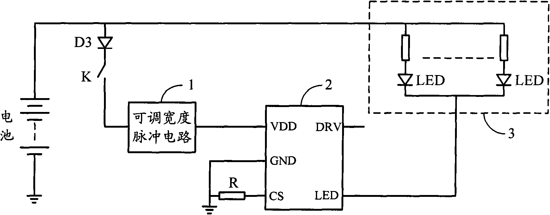
[0003] The purpose of the embodiments of the present invention is to provide a battery discharge circuit, aiming to solve the problem that the pulse width ratio of the existing battery discharge circuit is fixed and it is difficult to prolong the battery discharge time

Method used


Image

  • Battery discharge circuit, power supply and LED lamp
  • Battery discharge circuit, power supply and LED lamp

Examples


Embodiment Construction

[0019] In order to make the object, technical solution and advantages of the present invention clearer, the present invention will be further described in detail below in conjunction with the accompanying drawings and embodiments. It should be understood that the specific embodiments described here are only used to explain the present invention, not to limit the present invention.

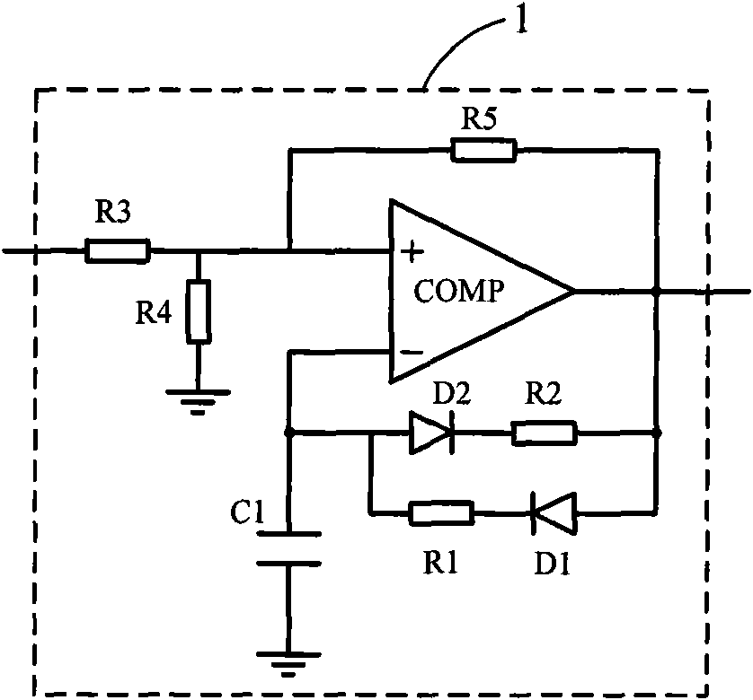
[0020] In the embodiment of the present invention, the oscillating working circuit in the battery discharge circuit is designed as a pulse circuit with adjustable width, and the pulse width is adjusted by changing circuit parameters to prolong the battery discharge time.

[0021] figure 1 The structure of the discharge circuit provided by the embodiment of the present invention is shown, and for the convenience of description, only the parts related to the embodiment of the present invention are shown.

[0022] In the embodiment of the present invention, the discharge circuit includes an adjustabl...


PUM


Abstract

The invention is applicable to the field of power supplies, in particular to a battery discharge circuit, a power supply and an LED lamp, the circuit comprises a constant-current drive control chip, an adjustable width pulse circuit and a battery discharge passage, wherein the constant-current drive control chip is used for outputting constant-current drive current; the adjustable width pulse circuit is series-connected between a positive end of a battery and a pin of the power supply of the constant-current drive control chip and used for changing the resistance of a charge-discharge resistor, outputting the adjustable width pulse and regulating the high-level duty cycle; and the battery discharge passage is series-connected between the positive end of the battery and a drive pin of the constant-current drive control chip and used for receiving the drive current outputted by the constant-current drive control chip. An oscillation working circuit in the battery discharge circuit is designed to the adjustable width pulse circuit, and the discharge time of the battery is prolonged by changing circuit parameters and adjusting the pulse width.

Description

technical field [0001] The invention belongs to the field of power supplies, and in particular relates to a battery discharge circuit, a power supply and an LED lamp. Background technique [0002] The current battery discharge circuit cannot adjust the pulse width because the pulse width ratio of the oscillating working circuit is fixed, so that the battery discharge time cannot be extended. Contents of the invention [0003] The purpose of the embodiments of the present invention is to provide a battery discharge circuit, aiming at solving the problem that the pulse width ratio of the existing battery discharge circuit is fixed and it is difficult to prolong the battery discharge time. [0004] The embodiment of the present invention is achieved in this way, a battery discharge circuit, the circuit includes: [0005] Constant current drive control chip, used to output constant current drive current; [0006] The adjustable width pulse circuit is connected in series betw...

Claims


Application Information

Patent Timeline
Patent Type & Authority Patents(China)
IPC IPC(8): H02M3/04H05B37/02
CPCY02B20/40
Inventor 周明杰王学军
Owner OCEANS KING LIGHTING SCI&TECH CO LTD
Learn More