Harmonic compensation method and device of PFC circuit and terminal device

A harmonic compensation and circuit technology, applied in the direction of output power conversion devices, electrical components, high-efficiency power electronics conversion, etc., can solve the problem of excessive input harmonics of PFC circuits, achieve calculation and ensure control stability, Calculatively simple effect

Active Publication Date: 2020-11-27
KEHUA DATA CO LTD +1
View PDF7 Cites 1 Cited by
  • Summary
  • Abstract
  • Description
  • Claims
  • Application Information

AI Technical Summary

Problems solved by technology

[0004] In view of this, an embodiment of the present invention provides a harmonic compensation method, device, and te

Method used


Image

  • Harmonic compensation method and device of PFC circuit and terminal device
  • Harmonic compensation method and device of PFC circuit and terminal device
  • Harmonic compensation method and device of PFC circuit and terminal device

Examples


Embodiment Construction

[0023] In the following description, for the purpose of illustration rather than limitation, specific details such as specific system structures and technologies are set forth in order to provide a thorough understanding of the embodiments of the present invention. However, it will be apparent to those skilled in the art that the present invention may be practiced in other embodiments without these specific details. In other instances, detailed descriptions of well-known systems, devices, circuits, and methods are omitted so as not to obscure the description of the present invention with unnecessary detail.

[0024] In order to illustrate the technical solutions of the present invention, the following specific embodiments are used for description.

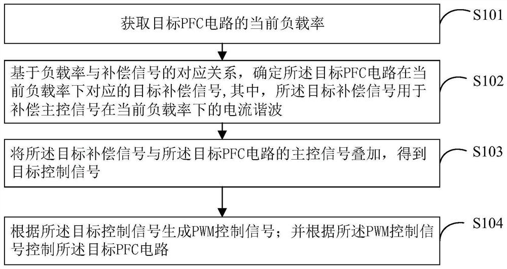
[0025] In one embodiment of the present invention, as figure 1 shown, figure 1 The realization flow of harmonic compensation of PFC circuit is shown, and its process is detailed as follows:

[0026] S101: obtain the current load...


PUM


Abstract

The invention is suitable for the technical field of power electronics, and provides a harmonic compensation method and device for a PFC circuit and a terminal device, and the method comprises the steps: obtaining the current load rate of a target PFC circuit; determining a target compensation signal corresponding to the target PFC circuit under the current load rate based on the corresponding relationship between the load rate and the compensation signal, the target compensation signal being used for compensating the current harmonic of the main control signal under the current load rate; superposing the target compensation signal and a main control signal of a target PFC circuit to obtain a target control signal; generating a PWM control signal according to the target control signal; andcontrolling the target PFC circuit according to the PWM control signal. The original master control signal is compensated through the target compensation signal, so that the duty ratio of the PWM control signal is adjusted, the harmonic input of the circuit is reduced, the calculated amount is small and simple, the chip resource overhead is reduced, and the control stability is ensured.

Description

technical field [0001] The invention belongs to the technical field of power electronics, and in particular relates to a harmonic compensation method, device and terminal equipment for a PFC circuit. Background technique [0002] In computer servers, communication power systems and special processing, large-capacity DC power supplies are usually required. When the load requires the power supply to provide thousands of amperes or even higher currents, if a single power supply is used, the switching stress of the switch tube and rectifier diode will be become very impressive. The staggered parallel PFC (Power Factor Correction, power factor correction) circuit can reduce the effective value of the input current ripple and the output capacitor ripple current without increasing the switching loss, increase the input current ripple frequency, and improve the power level of the circuit , so the PFC circuit has high application value. [0003] Since the input harmonics of the PFC...

Claims


Application Information

Patent Timeline
IPC IPC(8): H02M1/12H02M1/42
CPCH02M1/12H02M1/42Y02B70/10
Inventor 卢雄伟陈威龙许永志唐新雨
Owner KEHUA DATA CO LTD
Why Eureka
Try Eureka