Image stitching method and device

An image stitching and image technology, applied in the field of image processing, can solve problems such as inability to perform image stitching and inability to calculate images.

Inactive Publication Date: 2010-05-19
GLOBAL INNOVATION AGGREGATORS LLC
View PDF0 Cites 87 Cited by
  • Summary
  • Abstract
  • Description
  • Claims
  • Application Information

AI Technical Summary

Problems solved by technology

[0007] In the process of applying the above scheme, the inventors of the present invention found that the corresponding homography matrix can be calculated only when there is a relatively large overlapping area between the above-mentioned mosaic-based images. For images with no overlapping area or only one column of overlapping pixels The homography matrix cannot be calculated, so image stitching cannot be performed

Method used


Image

  • Image stitching method and device
  • Image stitching method and device
  • Image stitching method and device

Examples


Embodiment 1

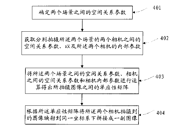
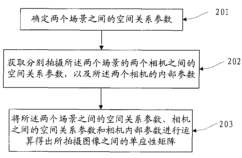
[0049] If two cameras shoot two scenes separately to obtain the images of the two scenes; or one camera shoots the two scenes separately to obtain the images of the two scenes, in order to stitch the two scenes together , it is necessary to calculate the homography matrix between two images. Embodiment 1 of the present invention provides a method for calculating the homography matrix between cameras, such as figure 2 As shown, the method includes:

[0050]201. Determine the spatial relationship parameter between two scenes, the spatial relationship parameter can be expressed by a function, assuming that one of the scenes is represented by P 1 , another scenario P 2 , then the spatial relationship parameter can be passed through P 2 =f(P 1 )To represent;

[0051] 202. Obtain the spatial relationship parameters between the two cameras that shoot the two scenes respectively, and the internal parameters of the two cameras; the spatial relationship parameters are also called e...

Embodiment 2

[0077] The application of the embodiment of the present invention is described below by taking the image of a large checkerboard as an example. First, make a Figure 6 As shown in the large checkerboard, there are two areas to be photographed surrounded by lines 1 and 2 in the large chessboard, and the sizes of these two areas to be photographed can be adjusted according to actual needs. The black grid or the white grid in the above-mentioned checkerboard are generally squares or rectangles of known size, because the size of the middle grid of the chessboard is known, so the positional relationship of the three-dimensional space of the two areas to be photographed can be known or solved (that is: two The spatial relationship parameters between scenes), that is to say, any pair of grids in the area to be photographed is selected, and the relative positional relationship between them is known or obtainable.

[0078] Secondly, the left and right cameras are used to simultaneously...

Embodiment 3

[0112] In this example, it is assumed that P 1 ,P 2 are two points in two scenes, and the spatial position relationship between the two scenes is: P 2 =f(P 1 ) = P 1 +b, and assume that K, K′ are the internal parameter matrices of the left and right cameras respectively, [R 1 t 1 ], [R 2 t 2 ] are the external parameters of the left and right cameras (together they can represent the spatial relationship between the cameras), and [R t] is the rotation matrix and translation vector of the right camera relative to the left camera.

[0113] Suppose P 1 ,P 2 , and the corresponding image coordinates are p 1 ,p 2 , then there is: P 1 ,P 2 The corresponding point in the camera coordinate system is P c1 ,P c2 , then there are:

[0114] P 1 = R 1 P c 1 ...


PUM


Abstract

The invention discloses an image stitching method and a device, relating to the field of image processing technology, and solves the problem the existing homography matrix needs an overlap area between the images or a video sequence; in the embodiment of the invention, spatial relationship parameters between two scenes are firstly determined; the spatial relationship parameters between two cameras for respectively shooting the two scenes and internal parameters of the two cameras are obtained; the homography matrix among the shot images is obtained by operating the spatial relationship parameters between the two scenes, the spatial relationship parameters between the cameras and the internal parameters of the camera; the images shot by the two cameras are mapped to the same coordinate system, so as to stitch one image according to the homography matrix; the embodiment of the invention is mainly applied to the calculation of the homography matrix between two images, especially applied to the calculation of the homography matrix in the image stitching process.

Description

technical field [0001] The invention relates to the technical field of image processing, in particular to an image splicing method and device. Background technique [0002] Seamless wide-angle images can be created directly through anti-refractive systems, fisheye lenses and other hardware devices, but because these hardware devices capture as much information as possible on a limited imaging surface, the seamless wide-angle images created are severely distorted . [0003] By using digital imaging equipment to capture images in digital format, multiple digital images can be spliced ​​to obtain a digital panoramic image with a wider field of view, and the finally obtained digital panoramic image has less distortion. Image stitching mainly includes the following steps: image acquisition, image preprocessing, image registration, image reprojection, and image fusion. [0004] Image registration is a key step in image stitching. It is necessary to find out the overlapping areas...

Claims


Application Information

Patent Timeline
Patent Type & Authority Applications(China)
IPC IPC(8): H04N1/387H04N5/262
CPCG06T7/002G06T2207/20221H04N5/2624G06T2207/20032G06T2207/10012G06T2207/10024G06T3/0068G06T7/85
Inventor 李凯
Owner GLOBAL INNOVATION AGGREGATORS LLC
Why Eureka
Try Eureka