
Multi-lobe artificial spine joint

A bulge, artificial technology, applied in spinal implants, medical science, prosthesis, etc., can solve problems such as aggravating the instability of artificial joints and accelerating joint problems

Active Publication Date: 2010-05-26
达美康公司
View PDF4 Cites 4 Cited by
  • Summary
  • Abstract
  • Description
  • Claims
  • Application Information

AI Technical Summary

Problems solved by technology

This effect can cause degeneration and inability to normal movement and control of the artificial joint, which can aggravate the instability of the artificial joint and may accelerate further joint problems

Method used


Image

  • Multi-lobe artificial spine joint
  • Multi-lobe artificial spine joint
  • Multi-lobe artificial spine joint

Examples


Embodiment Construction

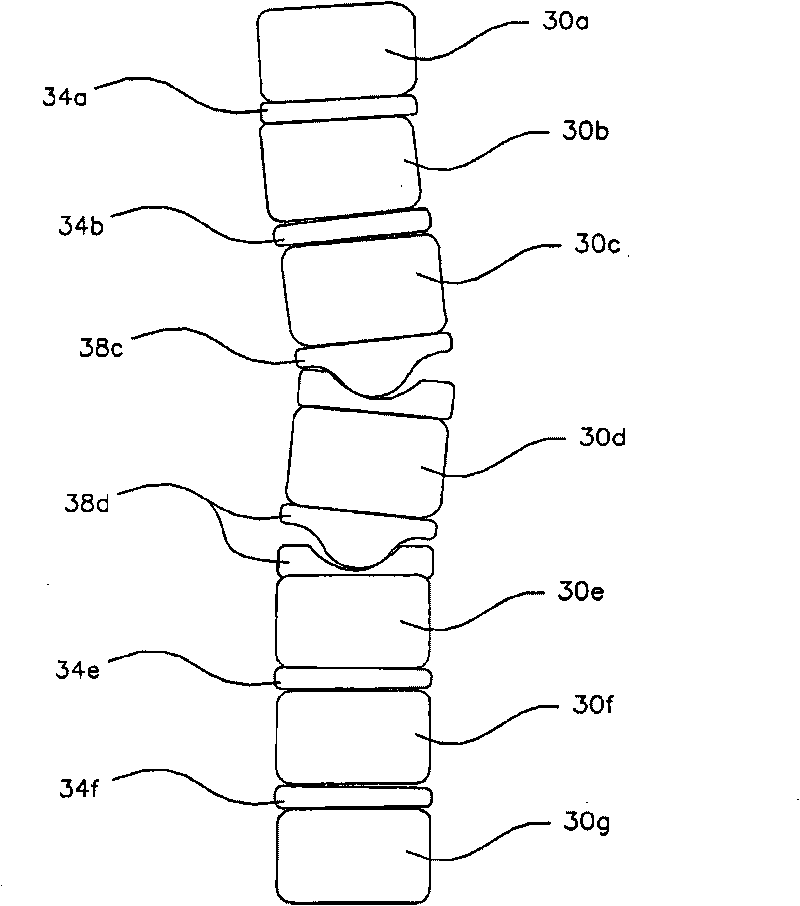
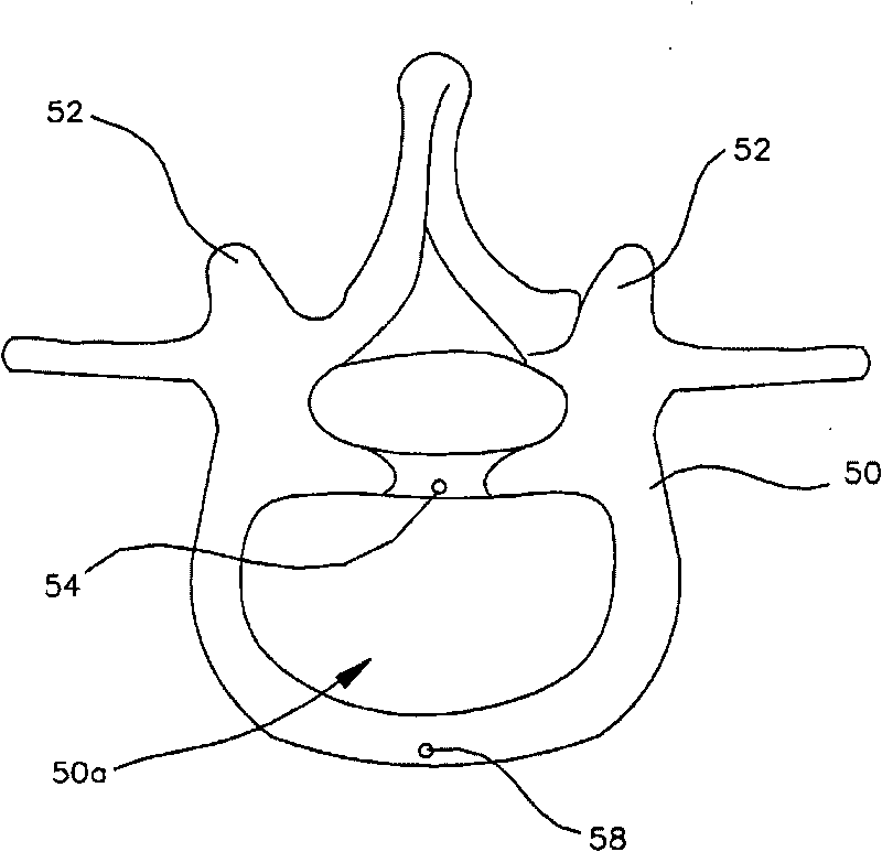
[0071] The present invention will now be discussed with reference to the accompanying drawings and the reference numerals provided therein to enable those skilled in the art to practice the invention. The drawings and description are representative of the various aspects of the invention and are not intended to limit the scope of the appended claims. In some of the figures, spaces are shown between adjacent structures that generally touch each other in order to more clearly illustrate the structures.

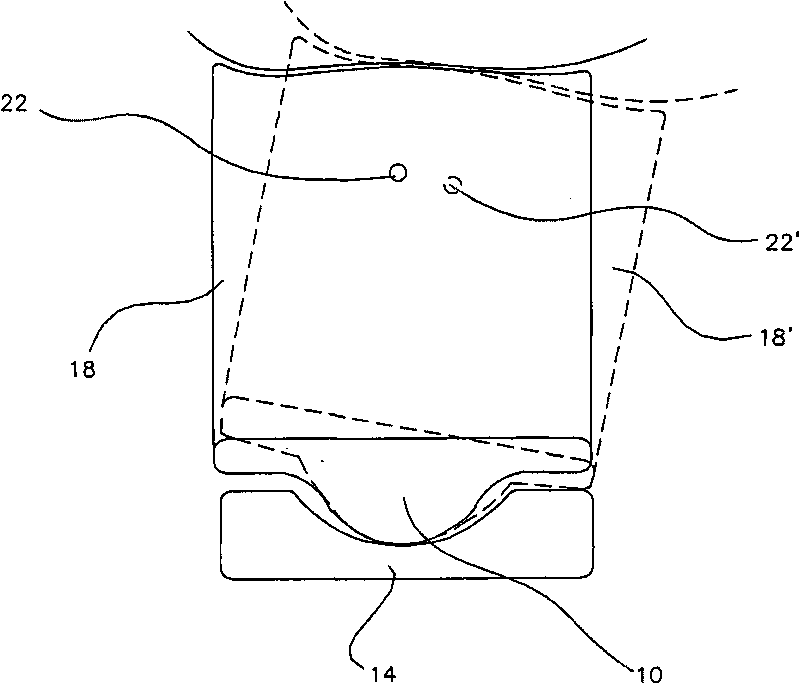
[0072] Currently, many artificial discs are currently available, or are being tested. These artificial discs often lack the stability of the natural spine. These prior art joints generally include a bearing surface that includes a cup-shaped receptacle on top of a spherical surface or a ball or spherical surface 10 placed in a cup-shaped receptacle 14 as shown in FIG. 1 . These joints move by pivoting in a similar manner to other known ball joints. Rectangle 18 generally repr...


PUM


Abstract

The invention provides an artificial disc which more closely matches the movement of the natural spine. The artificial disc uses one or more projections and corresponding recesses to provide a sliding articulation. The artificial joint is inherently stable in that compressive forces placed on the disc such as the weight placed upon the joint or the tension of surrounding tissues urges the joint towards a neutral position and not farther away from a neutral position.

Description

technical field [0001] The present invention relates to various artificial joints and, in particular, to an artificial intervertebral disc for replacing a damaged spinal disc. The present invention relates to an improved artificial intervertebral disc for use in both total disc replacement and nuclear replacement. Background technique [0002] Artificial joints are becoming more and more common for treating degenerated bone joints. Joints can be damaged by accident, disease, aging, etc., and are often replaced when painful enough, or when enough to impair the joint's natural movement. Artificial joints generally replace tissue between adjacent bones, and may often replace the ends of two adjacent bones that form the joint. [0003] There are generally several desired outcomes to be achieved when replacing a joint. These results include: stability, load bearing capacity, maintenance of natural motion, pain relief, and reduced rate of damage and reduction in severe damage. ...

Claims


Application Information

Patent Timeline
Patent Type & Authority Applications(China)
IPC IPC(8): A61F2/44
CPCA61F2002/30369A61F2002/30365A61F2/4425A61F2230/0065A61F2002/30138A61F2002/30158A61F2002/443A61F2002/302A61F2230/0017A61F2002/449A61F2220/0033A61F2002/444A61F2002/30934A61F2230/0026A61F2/30742A61F2/44A61F2/442
Inventor B-K·N·源D·P·哈丁
Owner 达美康公司
Learn More