
Contact-breaker device, circuit and apparatus comprising the same, and method for assembling contact-breaker device

A component and circuit technology, applied in the field of high-potential irregular pulse current generators, can solve problems such as difficult to obtain effects, the handle of the toothbrush is accommodated in a small space, and the life of the battery is shortened.

Inactive Publication Date: 2009-07-08
FUKUBA DENTAL
View PDF8 Cites 0 Cited by
  • Summary
  • Abstract
  • Description
  • Claims
  • Application Information

AI Technical Summary

Problems solved by technology

Therefore, as described in Non-Patent Document 2, habituation will occur to physical stimuli, and the response to the stimulus will be weakened, and it will be difficult to obtain good effects in the long run.
[0012] In addition, as recorded in the Encyclopedia of Electronic Therapy published by Kenyoukan in 1993, edited by Tsukuba University honorary professor, doctor of medicine, Yasushi Saburo, when the waveform or frequency of the low-frequency current is changed, the body will not be effective for activation. In the case of a regular pulse current, in order to generate the irregular pulse current, even if you want to use the switches described in JP-A-6-290690, JP-A-11-73831, and JP-A-9-108453, there will be the following problems : As mentioned above, these switches are difficult to miniaturize, so there is a defect that for example, the handle of a toothbrush cannot be accommodated in a small space
Moreover, switches in the prior art (for example, pulse and digital circuits, etc.) consume a lot of power. For example, when a battery is used as a power source, the life of the battery will be shortened, so the battery must be replaced frequently. Switches in technology are costly, so the cost of housing these products (e.g. toothbrushes, etc.) will also increase

Method used


Image

  • Contact-breaker device, circuit and apparatus comprising the same, and method for assembling contact-breaker device
  • Contact-breaker device, circuit and apparatus comprising the same, and method for assembling contact-breaker device
  • Contact-breaker device, circuit and apparatus comprising the same, and method for assembling contact-breaker device

Examples


Embodiment 2

[0128] Next, a discontinuous element according to Embodiment 2 of the present invention will be described with reference to the drawings. In addition, in the second embodiment, the same components as those already described in the first embodiment are denoted by the same reference numerals, and detailed description thereof will be omitted.

[0129] Figure 11 is a cross-sectional view of the intermittent element involved in the second embodiment, Figure 12 is along Figure 11 A cross-sectional view taken along the line C-C shown.

[0130] Such as Figure 11 and Figure 12 As shown, the structure of the intermittent element 50 according to the second embodiment includes: a substantially cylindrical connection member 17 formed of an insulator; fixed terminals 52A and 52B arranged separately from each other through the connection member 17; and a similar case 51 .

[0131] The fixed terminals 52A and 52B include a closed portion 53 and a cylindrical portion 54, the closed p...

Embodiment 3

[0137] Next, the pulse current generating device related to Embodiment 3 of the present invention will be described with reference to the accompanying drawings. In addition, the same components as those described in Embodiment 1 and Embodiment 2 in Embodiment 3 will be marked with the same , and its detailed description is omitted.

[0138] Figure 13 It is a side view of the cosmetic device as a pulse current generating device related to the third embodiment, a part of which is shown in cross-section.

[0139] Such as Figure 13 As shown, the main structural difference between the beauty device 70 involved in the embodiment and the ionic toothbrush described in the first embodiment lies in the structure of the brush head 127 . The head end side of the brush head 127 is a hair-planting part 71 , on the surface of one side of the hair-planting part 71 , a sponge 72 is arranged, and bristles 73 are planted around the sponge 72 . In addition, a sponge 74 having different chara...

Embodiment 4

[0143]Next, a pulse current generator according to Embodiment 4 of the present invention will be described with reference to the drawings. In addition, in the fourth embodiment, the same components as those described in the above-mentioned embodiments are denoted by the same reference numerals, and detailed description thereof will be omitted.

[0144] Figure 14 It is a side view of a massager as a pulse current generating device according to Embodiment 4, and a part thereof is shown in cross section.

[0145] Such as Figure 14 As shown, the main structural difference between the massager 80 involved in the fourth embodiment and the ionic toothbrush 1 described in the first embodiment lies in the structure of the brush head 227 . Like the first embodiment, a conductive component insertion hole 63 is formed inside the brush head 227 , and the conductive component insertion hole 63 penetrates to the front end of the brush head 227 .

[0146] A finger-pressing part 81 made o...


PUM


Abstract

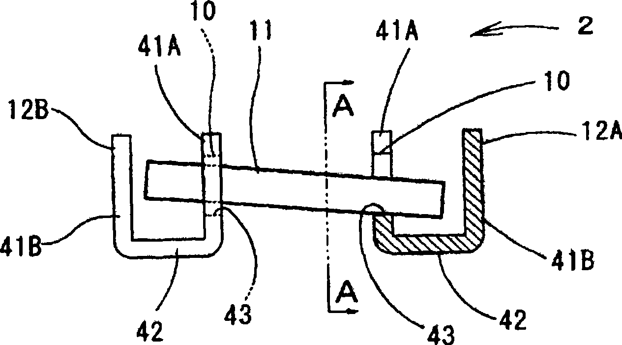
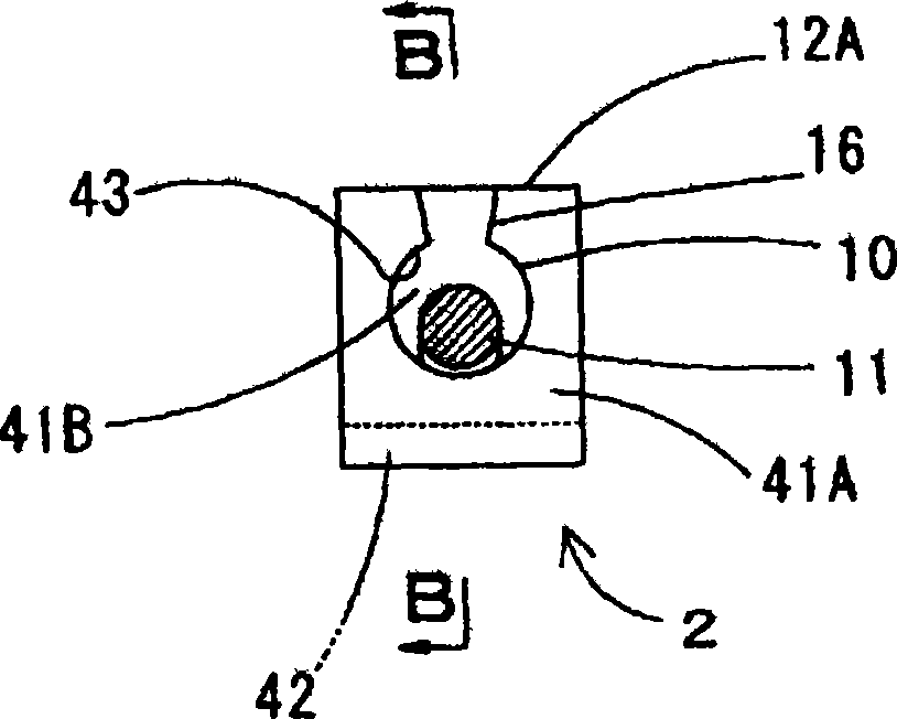
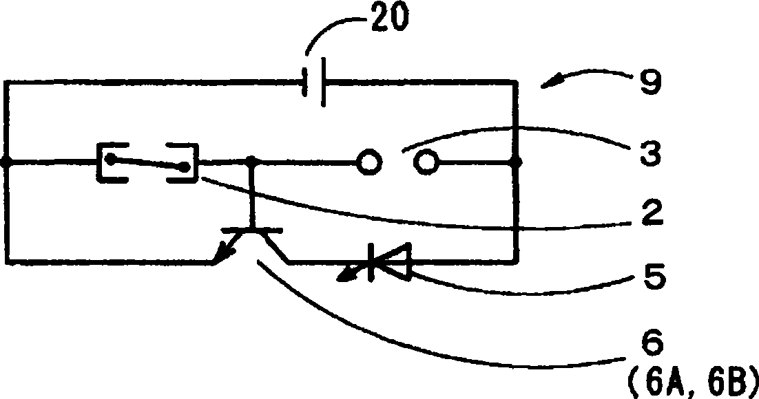
The invention discloses a discontinuous element capable of realizing miniaturization, low power consumption and low cost. The discontinuous element can generate irregular pulse current by making the circuit conduct and insulate irregularly, which includes: Separately fixed fixed terminals (12A) and (12B); and a movable part (11), which can move freely relative to the fixed terminals (12A) and (12B), and through this movement, the movable part and the fixed The terminals (12A) and (12B) are in contact or non-contact, thereby making the fixed terminal conductive or insulated, and the movable part (11) performs the movement irregularly according to the vibration applied from the outside, so that the fixed terminal (12A) ) and (12B) are irregularly conducted and insulated.

Description

technical field [0001] The present invention relates to a discontinuous element, a circuit including the discontinuous element, a high-potential irregular pulse current generating circuit, a pulse current generating device including the circuit that can generate irregular pulse current, a high-potential irregular pulse current generating device, and A method of assembling an intermittent element that can irregularly switch a circuit in response to external vibrations. Background technique [0002] When detecting posture changes such as micro-vibration or tilt, there are spring switches or mercury contact switches in the prior art. In addition, Japanese Patent Laid-Open No. 6-290690 discloses a ball contact switch, which is characterized in that it solves the problems of elastic degradation of spring type switches or mercury contact switches, low sensitivity to fine-tuning methods and posture changes, and large shape. In a small switch, a ball contact having a conductive sur...

Claims


Application Information

Patent Timeline
Patent Type & Authority Patents(China)
IPC IPC(8): H01H35/14H01H35/02H01H9/16H03K3/00A61N1/32
Inventor 福场博池上确户沢奎三郎河野幸人佐伯公弘小林清志户边利男池上洁
Owner FUKUBA DENTAL
Learn More