Electric-optically Q-switched switch driver

A technology of switch drive and switch circuit, which is applied in the field of laser application to achieve the effect of simple switching and increased repetition frequency

Inactive Publication Date: 2010-06-02
HUAZHONG UNIV OF SCI & TECH
View PDF0 Cites 7 Cited by
  • Summary
  • Abstract
  • Description
  • Claims
  • Application Information

AI Technical Summary

Problems solved by technology

However, the two functions can only be switched one-to-one, that is, the mutual switching between one press

Method used


Image

  • Electric-optically Q-switched switch driver
  • Electric-optically Q-switched switch driver
  • Electric-optically Q-switched switch driver

Examples


Embodiment Construction

[0017] The present invention is described in more detail below by means of examples, but the following examples are only illustrative, and the protection scope of the present invention is not limited by these examples.

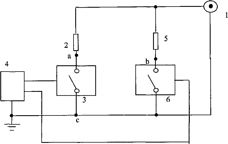
[0018] Such as figure 1 As shown, the electro-optical Q-switching switch driving power provided by the present invention includes a DC high voltage source 1 , first and second current limiting resistors 2 and 5 , first and second switching circuits 3 and 6 , and a trigger circuit 4 .

[0019] The positive voltage output terminals of the DC high voltage source 1 are respectively connected to one ends of the first and second current limiting resistors 2 and 5, and the other ends of the first and second current limiting resistors 2 and 5 are respectively connected to the first and second switching circuits 3 , 6 output terminals are connected, the control terminals of the first and second switch circuits 3 and 6 are respectively connected with the first and secon...


PUM


Abstract

The invention provides an electric-optically Q-switched switch driver, which comprises a DC high voltage source, and is characterized in that: the electric-optically Q-switched switch driver also comprises first and second current limit resistors, first and second switch circuits and a trigger circuit; the DC high voltage source, the first current limit resistor, the first switch circuit and a trigger signal form a voltage-decreased circuit; and the DC high voltage source, the second current limit resistor, the second switch circuit and a trigger signal form another voltage-decreased circuit. When used as a voltage-increased electric-optically Q-switched driver, the electric-optically Q-switched switch driver can chop laser pulses and compress laser pulse width; and when used as two voltage-decreased electric-optically Q-switched drivers, the electric-optically Q-switched switch driver is applied to a dual electric-optically Q-switched laser to double the repetition frequency.

Description

technical field [0001] The invention belongs to laser application technology, and in particular relates to a novel electro-optic Q-switching drive power supply. Background technique [0002] Electro-optic Q-switching technology is a technology that uses the electro-optic effect of crystals to realize Q-value mutations, compresses laser energy into extremely narrow pulses and emits them, so that the peak power of laser output can be increased by several orders of magnitude. The working mode of the electro-optical Q-switching switch is usually divided into two types: back pressure type and pressure type. The working principle of electro-optic Q-switching switch devoltage is as follows: When the potential difference between the two poles of the electro-optic crystal is high voltage, the loss in the laser resonator is very large, the Q value is small, and laser oscillation cannot be formed, and there is no laser output, which is called the electro-optic crystal. When the potent...

Claims


Application Information

Patent Timeline
IPC IPC(8): H01S3/11
Inventor 郭飞朱晓朱长虹朱广志齐丽君
Owner HUAZHONG UNIV OF SCI & TECH
Why Eureka
Try Eureka