
A floating mechanism and an annular air duct end sealing device

A floating mechanism, annular air duct technology, applied in furnace types, furnaces, lighting and heating equipment, etc., can solve problems such as strong liquid fluctuations, baffle scraping, vibration, etc.

Active Publication Date: 2011-12-28
ZHONGYE-CHANGTIAN INT ENG CO LTD
View PDF0 Cites 0 Cited by
  • Summary
  • Abstract
  • Description
  • Claims
  • Application Information

AI Technical Summary

Problems solved by technology

[0006] Due to the installation and processing errors of the annular cooler, the door-type sealing device may have radial and axial displacements of the annular cooler. When the cover plate of the door-type sealing device produces radial deviation and axial displacement, the door-shaped The scratch between the sealing device cover plate and the baffle may even damage the baffle and drive the baffle to move together
As a result, the cold air enters the non-cooling area directly from the door-type sealing device, causing the liquid in the annular liquid tank to fluctuate and vibrate strongly

Method used


Image

  • A floating mechanism and an annular air duct end sealing device
  • A floating mechanism and an annular air duct end sealing device
  • A floating mechanism and an annular air duct end sealing device

Examples


Embodiment Construction

[0050] The invention provides a floating mechanism, which is used to ensure the up and down floating and radial displacement of the floating part.

[0051]In order to make the above objects, features and advantages of the present invention more obvious and comprehensible, the floating mechanism of the present invention will be further described in detail below in conjunction with the accompanying drawings and specific embodiments.

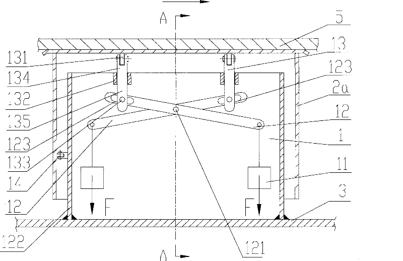
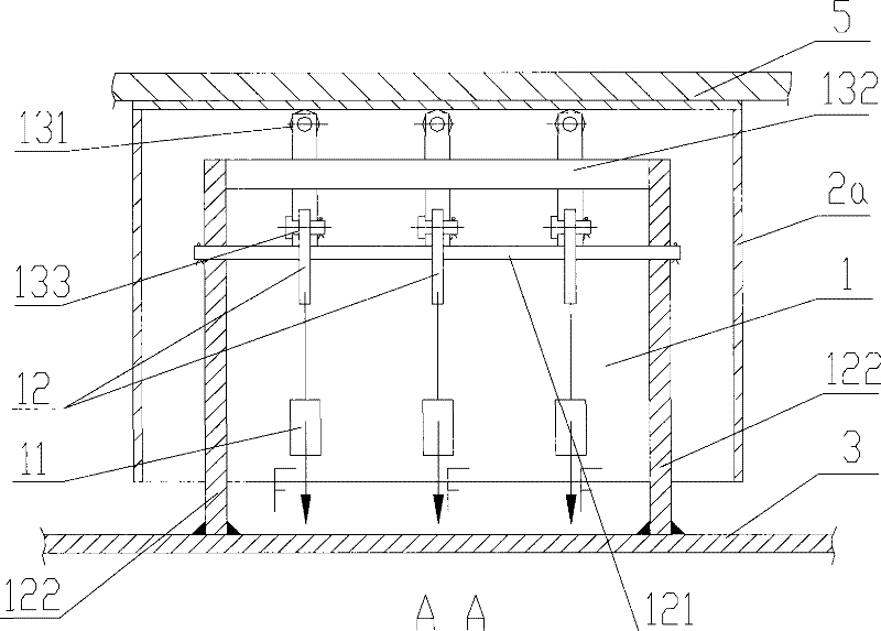
[0052] see figure 1 and figure 2 , figure 1 It is a structural diagram of an embodiment of the floating mechanism of the present invention; figure 2 Yes figure 1 Shown I-I is to the sectional view of the first embodiment.

[0053] The floating mechanism 1 described in the first embodiment of the present invention is used to support the floating member 2a. The floating mechanism 1

[0054] At least three levers 12 and radial pulley blocks 13 with the same number of levers 12 are included.

[0055] The floating member 2 a includes at least a...


PUM


Abstract

A floating mechanism is used to support the floating member. The floating mechanism includes at least three levers and radial pulley blocks with the same number as the levers. The three levers share a fulcrum, and the fulcrum is a cylinder; one end of each lever is applied with balance gravity, and the other end of each lever is provided with a first guide device that limits the movement of the pulley block along the axis of the lever. The fulcrum is fixedly installed on the workbench or track. The pulley block includes the same number of pulleys and pulley support mechanisms as the number of levers, and a second guide device for limiting the movement of the pulleys in the vertical direction. The pulley support mechanism includes a support body that moves along the second guide device, a guide block that is rigidly connected with one end of the support body and moves along the first guide device, and a guide block that is rigidly connected with the other end of the support body and is used to support the pulley. Pulley support. The invention also provides an end sealing device of the annular air duct, which is used to ensure the sealing of the end of the annular air duct.

Description

technical field [0001] The invention relates to a floating mechanism, in particular to a floating mechanism and an end sealing device of an annular air duct. Background technique [0002] The annular cooler generally uses air cooling to cool the material of the annular cooler trolley, but it does not need to be cooled in the unloading area of ​​the annular cooler trolley, and this area is called a non-cooling area. In order to ensure that the cold air does not leak in the non-cooling area, it is necessary to seal the end of the annular air duct. [0003] The double-layer trolley of the annular cooler is generally equipped with an annular air duct, and the cold air passing through the annular air duct cools the material of the annular cooler trolley. In order to ensure the cooling effect of the cooling zone and prevent the leakage of cold air, it is very important to seal the annular air duct. [0004] The existing better way to ensure air duct sealing is to adopt a liquid ...

Claims


Application Information

Patent Timeline
Patent Type & Authority Patents(China)
IPC IPC(8): F27B21/08
Inventor 高德亮
Owner ZHONGYE-CHANGTIAN INT ENG CO LTD
Learn More