Multifrequency antenna and electronic device with same

A technology for multi-frequency antennas and electronic devices, which is applied to devices, antennas, slot antennas and other directions that make the antennas work in different frequency bands at the same time, and can solve problems such as non-compliance with the bandwidth requirements of multi-frequency antennas.

Active Publication Date: 2010-06-09
WISTRON NEWEB
View PDF1 Cites 6 Cited by
  • Summary
  • Abstract
  • Description
  • Claims
  • Application Information

AI Technical Summary

Problems solved by technology

It can be seen that the frequency band that the antenna 90 in the prior art can transmit is very limited, and it does not meet the bandwidth requirements of today's multi-frequency antennas.

Method used


Image

  • Multifrequency antenna and electronic device with same
  • Multifrequency antenna and electronic device with same
  • Multifrequency antenna and electronic device with same

Examples


Embodiment Construction

[0044] In order to make the above and other objects, features and advantages of the present invention more comprehensible, specific embodiments of the present invention are listed below and described in detail in conjunction with the accompanying drawings.

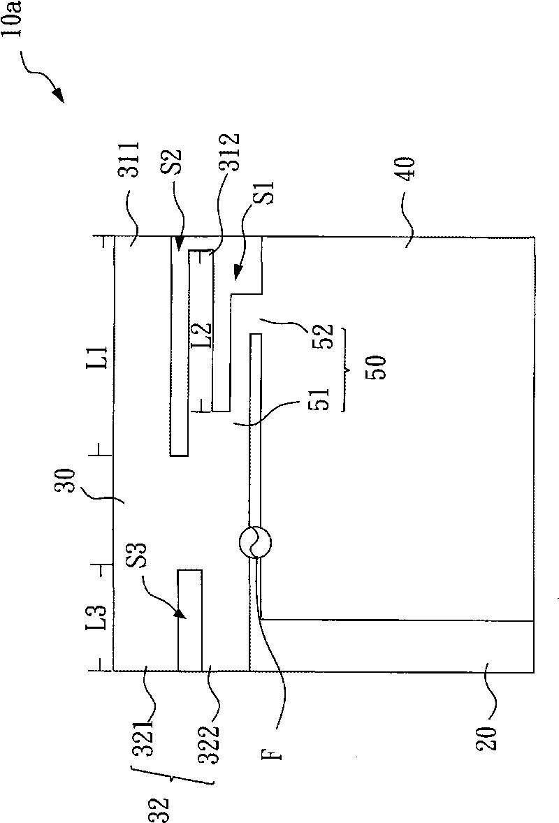
[0045] Please refer to Figure 2A , is a schematic diagram of the first embodiment of the multi-frequency antenna of the present invention.

[0046] In the first embodiment of the present invention, the multi-frequency antenna 10a is a planar structure. The multi-frequency antenna 10 a includes a substrate 20 , a radiating element (Radiating Element) 30 , a grounding element (Grounding Element) 40 , a shorting element 50 and a feeding point (feeding point) F. As shown in FIG. The substrate 20 is a printed circuit board, a plastic board or a glass fiber board, but the invention is not limited thereto. The radiation component 30 , the ground component 40 and the short circuit component 50 can be printed on the substrate 20...


PUM


Abstract

The invention relates to a multifrequency antenna and an electronic device with same. Specifically the invention is the multifrequency antenna used in the electronic device and for transmitting wireless signal. The multifrequency antenna comprises a substrate, a radiation component, a grounding component, a short-circuit component and a load point, wherein the radiation component, grounding component and short-circuit component are arranged on the substrate; the short-circuit component comprises a first end and a second end, the first end is connected with the radiation component and the second end is connected with the grounding component, wherein a first slot hole is arranged between the radiation component and the short-circuit component. The load point is used to feed electrical signals, wherein the load point is actually arranged between the side of the substrate and the short-circuit component. The invention can realize the effect of broadband transmission.

Description

technical field [0001] The invention relates to a multi-frequency antenna, in particular to a multi-frequency antenna which can utilize the adjustment slot to achieve broadband transmission. Background technique [0002] With the advancement of science and technology, the transmission of electronic products on the market using wireless communication systems has become more and more popular. For multimedia data that requires a large amount of data, a transmission antenna with a larger bandwidth is more needed. As a result, traditional antennas cannot meet the requirements. [0003] One type of antenna has been disclosed in the prior art. Please refer to the following Figure 1A There are schematic diagrams of antennas related to the prior art. A prior art antenna 90 is disclosed in US Patent Publication No. 6,812,892B2. The prior art antenna 90 has a radiation element 91 , a connection element 92 , a ground element 93 and a feed point F. As shown in FIG. The connection e...

Claims


Application Information

Patent Timeline
Patent Type & Authority Applications(China)
IPC IPC(8): H01Q1/38H01Q5/00H01Q9/04H01Q13/10H01Q5/20H01Q5/328H01Q5/335
Inventor 林建宏江毓彧张源利
Owner WISTRON NEWEB
Why Eureka
Try Eureka