Eureka AIR delivers breakthrough ideas for toughest innovation challenges, trusted by R&D personnel around the world.

Imaging apparatus

A technology for photographic devices and subjects, applied to focusing devices, instruments, televisions, etc., can solve the problems of AF accuracy reduction and errors

Active Publication Date: 2013-04-17
OM DIGITAL SOLUTIONS CORP
View PDF4 Cites 0 Cited by
  • Summary
  • Abstract
  • Description
  • Claims
  • Application Information

AI Technical Summary

Problems solved by technology

Therefore, when a CMOS sensor is used as an imaging element, an error in the focus lens position corresponding to the amount of change in the exposure time corresponding to the line of the subject position within the shooting screen occurs, and the AF accuracy decreases.

Method used


Image

  • Imaging apparatus
  • Imaging apparatus
  • Imaging apparatus

Examples


Embodiment Construction

[0055] Next, a first embodiment of the present invention will be described with reference to the drawings.

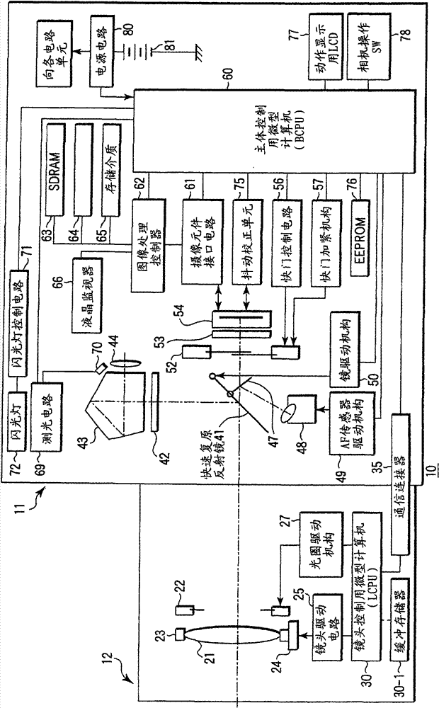
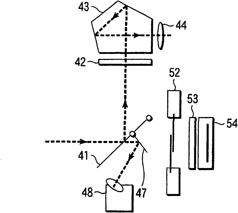
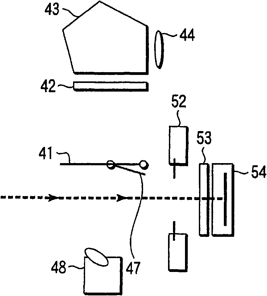
[0056] figure 1 A block diagram showing the structure of the imaging device. This imaging device 10 is composed of a main body unit 11 and, for example, an interchangeable lens unit (ie, lens barrel) 12 as an accessory device.

[0057] The lens unit 12 is detachably mounted on the main body unit 11 through a lens mount provided on the front surface of the main body unit 11 . The lens unit 12 is composed of a photographic lens 21 as a focusing lens, a diaphragm 22 , a lens frame 23 , a lens driving mechanism 24 , a lens driving circuit 25 , a diaphragm driving mechanism 27 , and a lens control microcomputer (hereinafter abbreviated as LCPU) 30 .

[0058] The photographic lens 21 is supported by a lens frame 23 . With regard to the photographing lens 21 , the lens frame 23 is moved in the direction of the optical axis P by the drive of a DC motor present in the lens d...


PUM


Abstract

An imaging apparatus of the invention comprises a camera body and a lens unit which can be mounted on and removed from the camera body. The focusing lens of the lens unit is moved along the optical axis. The position of the focusing lens on the optical axis is detected by a position detection section in response to a synchronization signal according to the photographic timing of the imaging device. A second transmission section transmits position data on the focusing lens detected by the position detection section to the camera body.

Description

[0001] This application claims the priority of Japanese Patent Application No. 2008-279589 filed on October 30, 2008 and Japanese Patent Application No. 2008-279588 filed on October 30, 2008, the entire contents of which are adopted by incorporated by reference into this patent application. technical field [0002] The present invention relates to an imaging device comprising a camera body and a lens unit (interchangeable lens unit) detachably attached to the camera body, and photographing a subject image on the side of the camera body through the lens unit. Background technique [0003] Some photographic devices include interchangeable-lens cameras including a camera body and a lens unit detachably attached to the camera body. The lens unit includes a lens unit including a focus lens and the like for adjusting a focus position to focus on a subject image. The camera body is equipped with an imaging element that captures a subject image formed by the lens unit. For example...

Claims


Application Information

Patent Timeline
Patent Type & Authority Patents(China)
IPC IPC(8): H04N5/225G03B13/36G03B17/14
CPCH04N5/23209H04N5/23212H04N23/663
Inventor 日暮正树
Owner OM DIGITAL SOLUTIONS CORP
Why Eureka
Eureka Blog
Learn More