Electronic apparatus equipped with detachable image pickup apparatuses, control method therefor, and storage medium storing control program therefor

Active Publication Date: 2018-09-27
CANON KK
View PDF6 Cites 5 Cited by
  • Summary
  • Abstract
  • Description
  • Claims
  • Application Information

AI Technical Summary

Benefits of technology

[0013]The present invention provides an electronic apparatus that achieves a function of a compound eye camera using a plurality of photographing modules a

Problems solved by technology

That is, a problem in use of a compound eye camera is that calibration relationship between modules is not stable within a usage environment range of a regular digital camera.
Moreover, signal levels of image signals output from a focus detecting pixel pair of an image pickup device may differ owing to imbalance in light amounts that enter into the focus detecting pixel pair through an exit pupil of a lens.
However, the techniques described in the above-mentioned public

Method used


Image

  • Electronic apparatus equipped with detachable image pickup apparatuses,  control method therefor, and storage medium storing control program  therefor
  • Electronic apparatus equipped with detachable image pickup apparatuses,  control method therefor, and storage medium storing control program  therefor
  • Electronic apparatus equipped with detachable image pickup apparatuses,  control method therefor, and storage medium storing control program  therefor

Examples


first embodiment

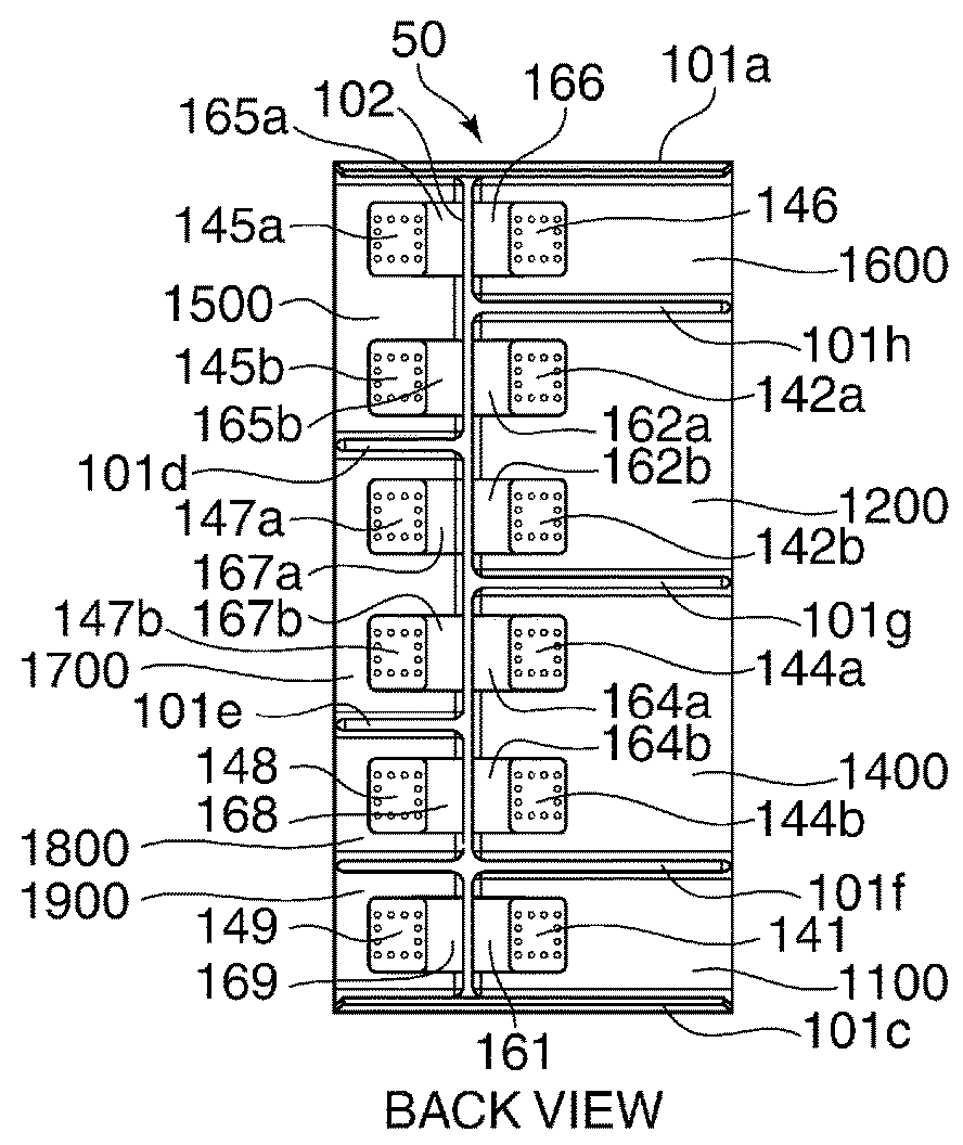
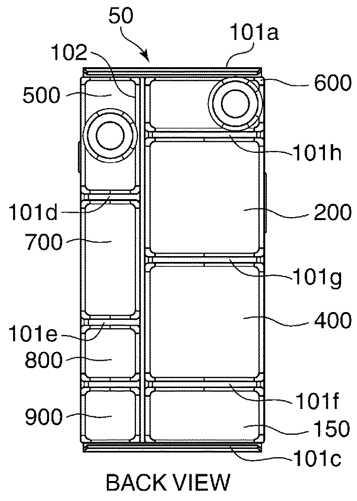
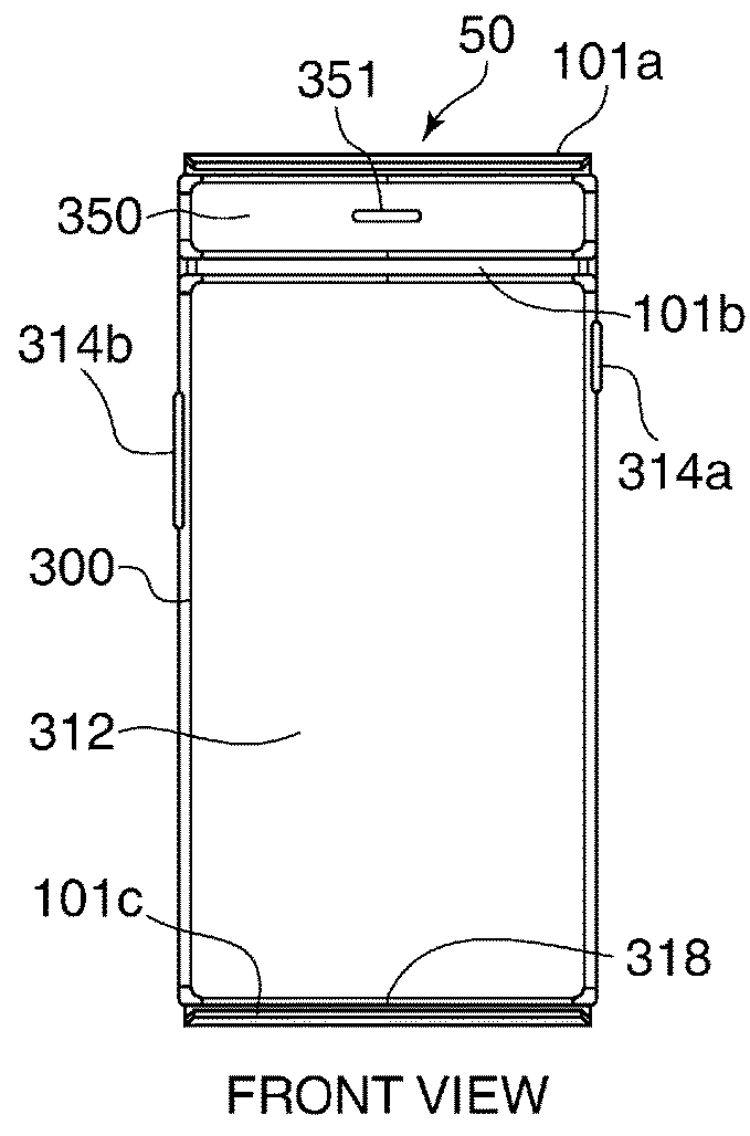
[0034]FIG. 1A through FIG. 1D are external views of a smart device 50 as an electronic apparatus according to the present invention.

[0035]FIG. 1A is an external view of a body of the smart device 50 viewed from a front side, and FIG. 1B is an external view of the body viewed from a back side.

[0036]As shown in FIG. 1A, a plurality of ribs 101a, 101b, and 101c are formed on the front side of the body of the smart device 50. Moreover, as shown in FIG. 1B, a plurality of ribs and a spine 102, which divides the body of the smart device 50 into right and left areas, are formed on the back side of the body of the smart device 50 in addition to the ribs 101a and 101c that are common with the front side. The ribs 101a through 101h and the spine 102 have a guiding function and holding function for a module to be attached, and have a function to improve rigidity of the body of the smart device 50. Hereinafter, the ribs 101a through 101h and the spine 102 are collectively referred to as a frame...

second embodiment

[0166]FIG. 14 is a flowchart showing procedures of the focusing position optimization process to a plurality of photographing modules executed in step S1505 in FIG. 10.

[0167]In step S1701 in FIG. 14, the application control circuit 210 instructs the attached photographing modules (the photographing modules 500 and 600 in the second embodiment) by sending a calibration start instruction message to the system control circuit 110. When receiving the calibration start instruction message through the system control circuit 110, the attached photographing modules 500 and 600 start the calibration operations for the cameras 510 and 610.

[0168]In step S1702, the application control circuit 210 calculates a base length that is a distance between the optical axis of the camera 510 and the optical axis of the camera 610. In the photographing execution process in the compound eye mode like this process, it is important to obtain a correct base length.

[0169]A threshold for difference between foc...


PUM


Abstract

An electronic apparatus that achieves a function of a compound eye camera using a plurality of photographing modules and that improves AF accuracy even if environmental conditions vary or even if a state is changed by impact from outside. The electronic apparatus includes two photographing modules. A first obtaining unit performs contrast AF by one of the two photographing modules to obtain a first focus detection result. A second obtaining unit calculates an object distance from parallax information between the two photographing modules to obtain a second focus detection result. A correction unit corrects a calculation result of the object distance obtained by the second obtaining unit in a case where a state of at least one of the two photographing modules and a body of the electronic apparatus varies and where a difference between the first and second focus detection results is more than a threshold.

Description

BACKGROUND OF THE INVENTIONField of the Invention[0001]The present invention relates to an electronic apparatus equipped with detachable image pickup apparatuses as modules, a control method therefore, and a storage medium storing a control program therefor.Description of the Related Art[0002]There is a well-known electronic apparatus called a smart device that achieves various desired functions by combining modules that are collected for functional units like blocks. Such a smart device consists of a body that has a plurality of slots and a plurality of modules that have different functions. These various modules are attached to the slots of the body in a free combination. Attachment of a photographing module to a slot of the body enables a photographing function by running an application program installed on an OS.[0003]There are various photographing modules corresponding to such a smart device. Focal length of an optical lens and size of an image sensor of a photographing module...

Claims


Application Information

Patent Timeline
IPC IPC(8): H04N5/232H04N5/238
CPCH04N5/23212H04N13/296H04N13/246H04N5/238H04N13/239H04N23/60H04N23/67H04N23/75
Inventor FUKAI, YOSUKENITTO, KIYOSHIOGAWA, TOSHIHIROIWAMATSU, JUNICHIRO
Owner CANON KK
Why Eureka
Try Eureka