
Adjustable orifice plate device and throttling governing method using same

A throttling orifice, adjustable technology, applied in valve device, valve details, valve shell structure and other directions, can solve the problem of fixed or unadjustable throttling area, and achieve the effect of large area adjustment ratio

Active Publication Date: 2011-05-25
CHINA SHENHUA ENERGY CO LTD +5
View PDF0 Cites 0 Cited by
  • Summary
  • Abstract
  • Description
  • Claims
  • Application Information

AI Technical Summary

Problems solved by technology

[0003] The throttling area is fixed and not adjustable;

Method used


Image

  • Adjustable orifice plate device and throttling governing method using same
  • Adjustable orifice plate device and throttling governing method using same
  • Adjustable orifice plate device and throttling governing method using same

Examples


Embodiment Construction

[0036] Hereinafter, specific embodiments of the present invention will be described in conjunction with the accompanying drawings.

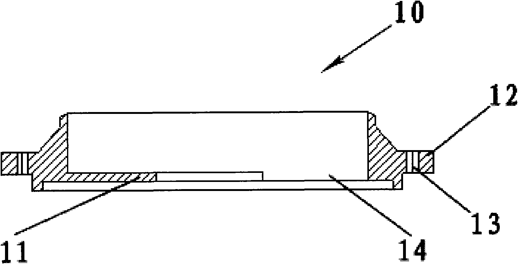
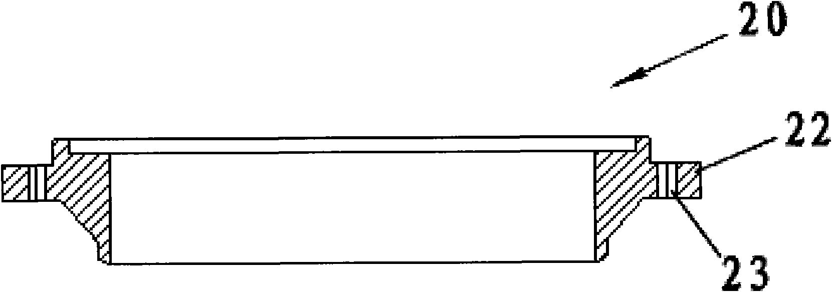
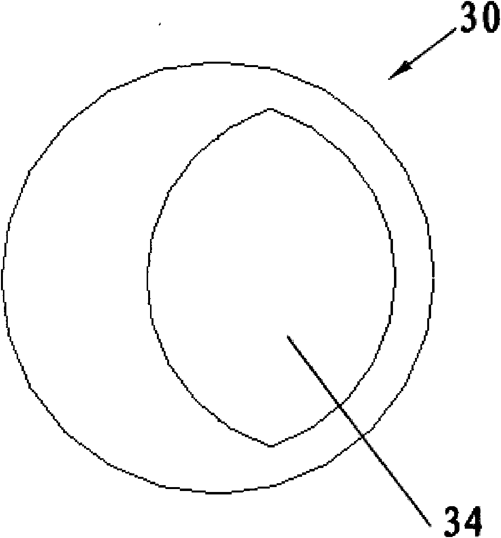
[0037] Such as Figure 1-Figure 4 As shown, the adjustable orifice device of the present invention includes: a flange with orifice 10, a flange without orifice 20, and an orifice 30; in addition, although not shown, the adjustable orifice device also includes There are washers, bolts and nuts etc.

[0038] Such as figure 1 As shown, the flange 10 with a throttle hole is internally provided with a throttle baffle 11 that reduces the flow area, so that a first flow hole 14 is formed on the plane where the throttle baffle 11 is located. A first flange 12 protrudes from the outer wall of the flange with orifice 10 in the radial direction, and the first flange 12 is provided with at least two first through holes 13 penetrating in the axial direction.

[0039] Such as figure 2 As shown, the non-restricted flange 20 has a second flange 22 protrudin...


PUM


Abstract

The invention relates to an adjustable orifice plate device which comprises an orifice flange, an orifice-free flange, an orifice plate, a gasket, a bolt and a nut, wherein the orifice flange is internally provided with a throttle baffle plate, a first flow through hole is formed on a plane on which the throttle baffle plate is arranged, the outer wall with the orifice flange is convexly providedwith a first flange along the radial direction, and a first through hole which axially runs through is arranged on the first flange; the outer wall of the orifice-free flange is convexly provided with a second flange along the radial direction, and the second flange is provided with a second through hole which axially runs through; the orifice plate is assembled between the orifice flange and theorifice-free flange, and a second flow through hole is arranged in the orifice plate; the gasket is arranged at two sides of the orifice plate and between the orifice flange and the orifice-free flange; and the bolt passes through the corresponding first through hole and the corresponding second through hole and is matched with the nut to enable the orifice flange to be fixedly connected with theorifice-free flange. By the invention, the flowing area can be changed according to the practical demands so that the adjustable orifice plate device can adapt to different fluid flowing requirements.

Description

technical field [0001] The invention relates to a throttling orifice device for adjusting flow in a pipeline, in particular to an adjustable orifice device for regulating flow and a throttling adjustment method using the device. Background technique [0002] A throttling orifice is usually provided on the process pipeline to adjust the flow rate. The traditional throttling orifice has a fixed area and cannot be adjusted, that is, the existing throttling orifice is all fixed. This throttle orifice has the following disadvantages: [0003] The throttling area is fixed and not adjustable; [0004] When the fluid flow requirements are not met, it is necessary to shut down the system related to the pipeline, remove the orifice plate, and process it to a suitable area; [0005] If the flow area needs to be reduced, a new throttle orifice needs to be replaced; Contents of the invention [0006] Therefore, in order to solve the above problems, the present invention proposes an...

Claims


Application Information

Patent Timeline
Patent Type & Authority Patents(China)
IPC IPC(8): F16K3/04F16K3/34F16K27/00F16L55/07
Inventor 张忠梅高峰张建丽杨庆卫周洪光丁涛李丁牛聚秦张奭李焱
Owner CHINA SHENHUA ENERGY CO LTD
Learn More