An adjustable throttling orifice device for ships

A throttle orifice, adjustable technology, applied in the direction of pipes/pipe joints/fittings, mechanical equipment, pipe components, etc., can solve the problem of time-consuming and material, the throttle orifice cannot meet the actual needs, etc., to save man-hours and materials, simple structure, high safety and reliability

Active Publication Date: 2017-02-15
HUDONG ZHONGHUA SHIPBUILDINGGROUP
View PDF10 Cites 0 Cited by
  • Summary
  • Abstract
  • Description
  • Claims
  • Application Information

AI Technical Summary

Problems solved by technology

However, in actual testing, it is often found that due to the deviation between the calculation results and the actual working conditions, the processed fixed orifice plate cannot meet the actual needs, so it is necessary to correct the data and re-manufacture the processing. Therefore, there are a lot of repeated calculations and Situations where manufacturing work results in a significant expenditure of man-hours and materials

Method used


Image

  • An adjustable throttling orifice device for ships
  • An adjustable throttling orifice device for ships
  • An adjustable throttling orifice device for ships

Examples


Embodiment Construction

[0039] Attached below picture Examples of the present invention will be described in detail, but the scope of protection of the present invention is not limited to the following examples.

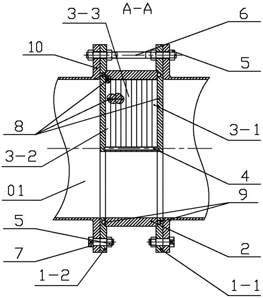
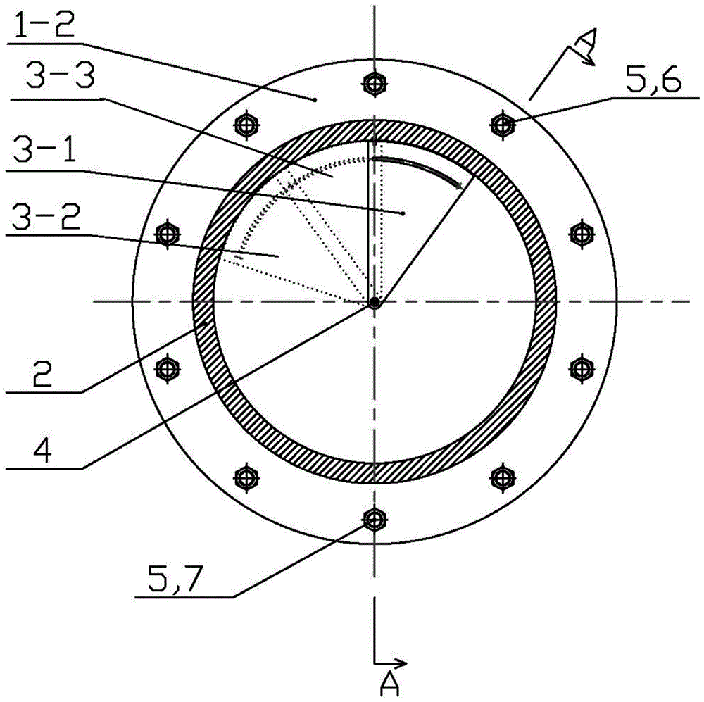
[0040] Please refer to figure 1 and figure 2 , picture It is shown that the adjustable throttle orifice device for ships is installed and connected in the pipeline for conveying fluid, and the pipes 01 on both sides of the pipeline connection are respectively provided with pipe flanges 10 . The throttle orifice device includes a left outer plate 1-2, a right outer plate 1-1, a rotary ring 2, a right inner plate 3-1, a left inner plate 3-2, a middle inner plate 3-3, and a pole 4 , positioning pin 8 and sealing ring 9.

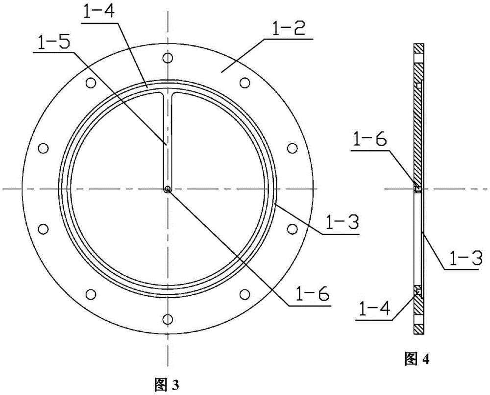
[0041] As shown in Figures 3 and 4, the left outer panel 1-2 is a hollow ring member, and a strip-shaped rib 1-5 extends from the ring to the center, and the rib 1-5 5 is located at the center of the ring body is provided with an impermeable central blind hole 1-6, t...


PUM


Abstract

The invention provides an adjustable restriction orifice device for a vessel. The adjustable restriction orifice device comprises a left external plate, a right external plate, a rotary ring, a right internal plate, a left internal plate, a middle internal plate, a supporting rod and a sealing ring, wherein the right external plate and the left external plate are respectively fixed by pipe flanges at two sides; two ends of the supporting rod are respectively inserted into middle blind holes of the left external plate and the right external plate; the right internal plate, the middle internal plate and the left internal plate are stacked and rotationally arranged on the supporting rod in a penetrating way and are sequentially connected with each other through positioning pins and arc guiding rail slots; the right internal plate is connected with the right external plate through the positioning pins; the sealing ring is embedded in an annular sealing slot between the right external plate and the left external plate; the rotary ring sleeves the periphery of the right internal plate, the middle internal plate and the left internal plate and is clamped between round grooves between the right external plate and the left external plate; the rotary ring is fixedly connected with the left internal plate through the positioning pins; the rotation of the rotary ring sequentially drives the left internal plate, the middle internal plate and the right internal plate to rotate and fold one by one through the sliding of the positioning pins in the arc guiding rail slots so as to adjust the flow area of fluid in the pipeline. The device is simple in structure, low in cost, convenient to operate and flexible to adjust.

Description

technical field [0001] The invention relates to a device for adjusting the flow area in a fluid pipeline, in particular to an adjustable throttling orifice device for ships, which belongs to the technical field of ship manufacturing. Background technique [0002] The fluid medium is usually transported in the ship piping system. In order to adjust the flow area of ​​the fluid in the pipeline to obtain the required fluid pressure and meet the requirements of fluid medium transportation, a throttling orifice plate is often used in the pipeline. The conventional throttling orifice is calculated to obtain the flow area of ​​the fluid in the pipeline, and then the throttling orifice is manufactured, installed and inspected according to the calculation results. Existing orifice plates are generally not adjustable. However, in actual testing, it is often found that due to the deviation between the calculation results and the actual working conditions, the processed fixed orifice p...

Claims


Application Information

Patent Timeline
Patent Type & Authority Patents(China)
IPC IPC(8): F16L55/027
CPCF16L55/02709
Inventor 段斌宋炜钱强
Owner HUDONG ZHONGHUA SHIPBUILDINGGROUP
Why Eureka
Try Eureka