
Lighting system

A lighting system and light source technology, applied in the field of lighting systems, can solve problems such as changing the light shape and being unable to use medical treatment

Inactive Publication Date: 2010-06-23
IND TECH RES INST
View PDF3 Cites 8 Cited by
  • Summary
  • Abstract
  • Description
  • Claims
  • Application Information

AI Technical Summary

Problems solved by technology

[0002] Generally, the optical design of high concentration can combine the light source with a secondary lens or a forward reflector to achieve the required light shape or projection state, but the lens cannot change the light shape without affecting the light output efficiency, and the forward reflector will Some light rays cannot be converged at a light angle of 10 to 45 degrees, so they cannot be used for special purposes such as medical treatment

Method used


Image

  • Lighting system
  • Lighting system
  • Lighting system

Examples


Embodiment Construction

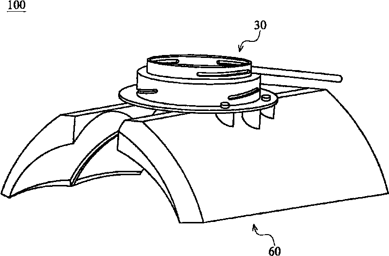
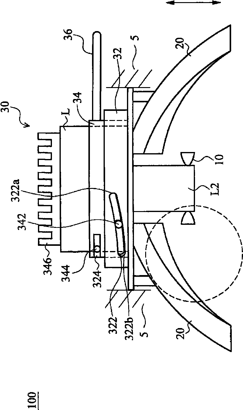
[0042] The lighting system of the present invention is as figure 1 , figure 2 as shown, figure 1 is a perspective view of an embodiment of the lighting system of the present invention, figure 2 for figure 1 side view.

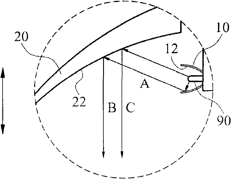
[0043] like figure 1 As shown, the lighting system 100 of an embodiment of the present invention includes a plurality of lighting modules 60 and a mechanism 30, referring to figure 2 and image 3 , each lighting module 60 includes a first reflector 10 , a second reflector 20 and a light source 90 .

[0044] The light source 90 is arranged in the first reflector 10, such as image 3 As shown, the first reflector 10 includes a first reflective surface 12, the second reflector 20 includes a second reflective surface 22, the light emitted by the light source 90 will have two situations, one of which is caused by the first reflector 10 The first reflected light A is formed after being reflected by the first reflective surface 12 of the second reflector 20...


PUM


Abstract

The invention discloses a lighting system, which includes at least one lighting module and a mechanism; the lighting module includes a light source, a first reflector and a second reflector. The first reflector includes a first reflection surface and the second reflector includes a second reflection surface. The light source generates a direct beam; the direct beam after being reflected by the first reflection surface generates a first reflection beam; the first reflection beam after being reflected by the second reflection surface generates a second reflection beam; the direct beam then is directly lighted on the second reflector to generate a third reflection beam; the second reflection beam and the third reflection beam generate a projection mode; the mechanism can move the second reflector or move the light source, thereby adjusting the relative positions of the second reflector and the light source so as to change the projection mode.

Description

technical field [0001] The invention relates to a lighting system, in particular to a lighting system with a reflector and a light source that can move relatively. Background technique [0002] Generally, the optical design of high concentration can combine the light source with a secondary lens or a forward reflector to achieve the required light shape or projection state, but the lens cannot change the light shape without affecting the light output efficiency, and the forward reflector will Some light cannot be converged at a light angle of 10 to 45 degrees, so it cannot be used for special purposes such as medical treatment. [0003] US Patent No. 4,037,036 discloses an optical design, which is a design proposed for traditional light sources, and mainly filters UV / IR light. The reflectors that pass through need to have the function of filtering UV / IR light. [0004] U.S. Patent No. 5,951,139 is a design proposed for traditional operating lights. Its structure is a combi...

Claims


Application Information

Patent Timeline
Patent Type & Authority Applications(China)
IPC IPC(8): F21S2/00F21V7/04F21V14/04F21Y101/02
Inventor 姜雅惠萧正达胡鸿烈杜冠洁
Owner IND TECH RES INST
Learn More