Double-wire welding control method

A control method and filler wire technology, applied in welding equipment, manufacturing tools, arc welding equipment, etc., can solve the problems of complex welding torch structure, high price, and high price, and achieve the effect of simple discrimination means

Active Publication Date: 2010-06-30
DAIHEN CORP
View PDF6 Cites 4 Cited by
  • Summary
  • Abstract
  • Description
  • Claims
  • Application Information

AI Technical Summary

Problems solved by technology

However, since the basic current value of tens of A is generally increased to a large current value of 200A or more, the state of droplet movement becomes temporarily unstable.
As a result, part of the appearance of the weld may deteriorate
[0018] In addition, when the method of prior art 3 described above is applied as an arc deflection countermeasure, it is necessary to specially arrange the front welding wire and the rear welding wire other than the filler wire in the welding torch, so the welding torch structure becomes complicated and expensive.
In addition, since a special power supply that supplies voltage to the front wire and the rear wire is also required, the price becomes higher

Method used


Image

  • Double-wire welding control method
  • Double-wire welding control method
  • Double-wire welding control method

Examples


Embodiment approach 1

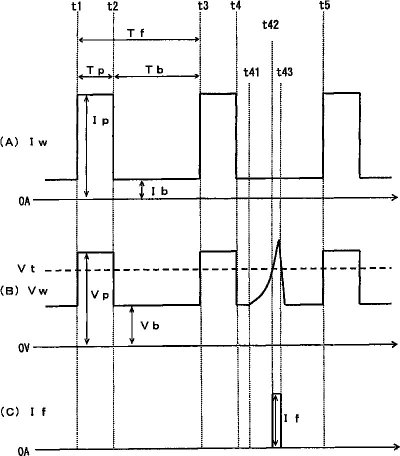
[0034] (Embodiment 1) figure 1 It is a current / voltage waveform diagram showing the twin wire welding control method according to Embodiment 1 of the present invention. The same figure (A) shows the change with time of the welding current Iw, the same figure (B) shows the change with time of the welding voltage Vw, and the same figure (C) shows the current If passed through the filler wire. In the same figure, in the pulse period from time t1 to t3, the stable welding state without arc deflection is shown, and in the following pulse cycle from time t3 to t5, the welding state in which arc deflection has occurred is shown. when. Hereinafter, the arc deflection countermeasure of the present embodiment will be described with reference to the same drawings.

[0035] During the pulse period from time t1 to t3, arc deflection does not occur, and thus the welding state is stable. During the peak period Tp from time t1 to time t2, as shown in (A) the peak current Ip is passed, and...

Embodiment approach 2

[0053] (Embodiment 2) Embodiment 2 differs from Embodiment 1 described above in the following points. That is, in Embodiment 1, when the occurrence of arc deflection is determined based on the rise of the base voltage Vb, the filling wire current If is started to flow. This operation is also the same in Embodiment 2. Furthermore, in Embodiment 1, when it is determined that the arc deflection is eliminated based on the drop in the base voltage Vb, the supply of the filler wire current If is stopped. On the other hand, in Embodiment 2, the filler wire current If is supplied only for a predetermined period after occurrence of arc deflection is determined. Hereinafter, Embodiment 2 will be described with reference to the drawings.

[0054] Figure 4 It is a waveform diagram showing the current / voltage of the twin wire welding control method according to Embodiment 2 of the present invention. The same figure (A) shows the time change of the welding current Iw, the same figure (...

Embodiment approach 3

[0061] (Embodiment 3) Embodiment 3 differs from the above-mentioned Embodiments 1 and 2 in the following points. That is, in Embodiments 1 and 2, when the occurrence of arc deflection is determined from the rise of the base voltage Vb, the supply of the filler wire current If is started. This operation is also the same in Embodiment 3. Furthermore, in Embodiment 1, when it is determined that the arc deflection is eliminated from the drop in the base voltage Vb, the supply of the filler wire current If is stopped. In addition, in Embodiment 2, the supply of the filler wire current If is stopped after a predetermined period of time elapses from the time when the generation of arc deflection is discriminated. On the other hand, in Embodiment 3, the fill current If is supplied during the period from when arc deflection is detected to when the next cycle of peak voltage Vp is applied to the welding wire (supply of peak current Ip). Hereinafter, Embodiment 3 will be described with...


PUM


Abstract

The invention provides a double-wire welding control method. In the double-wire welding control method, electric arc interrupt due to generation of electric arc deflection is restrained. The double-wire welding control method includes: repeatedly applying a peak voltage and applying a base voltage taken as a cycle between the consumption electrode and the mother plate, applying a welding current to generate electric arc to form a melting bath, and conveying the filler wire to the melting bath for welding, wherein when the electric arc deflexion generation (time t42) in electric arc is determined based on the ascending of the base voltage the ascend, a current is applied in the same direction to the welding current in the filler wire, to eliminate the electric arc deflexion (time t43). In order to apply the current in the same direction in the welding wire and the filler wire, a binding force is acted to the electric arc deflection due to electric arc deflexion, so as to normalize the electric arc deflection.

Description

technical field [0001] The present invention relates to a twin-wire welding control method for suppressing arc instability caused by arc deflection (magneticarc blow) in a twin-wire welding method in which a consumable electrode is placed between a consumable electrode and a base metal. During this period, by repeatedly applying the peak voltage and applying the base voltage as one cycle, an arc is generated to form a molten pool, and the filler wire is transported into the molten pool for welding. Background technique [0002] (Prior Art 1) As is well known, there is a conventional twin-wire welding method in which an arc is generated between a consumable electrode (hereinafter referred to as a welding wire) and a base metal to form a molten pool, and at the same time, a filler wire is fed to the molten pool and welded (see Patent Document 1). In this twin wire welding method, since the molten metal of the filler wire is added to the molten metal of the welding wire, the a...

Claims


Application Information

Patent Timeline
Patent Type & Authority Applications(China)
IPC IPC(8): B23K9/00
Inventor 盐崎秀男上山智之
Owner DAIHEN CORP
Why Eureka
Try Eureka