
Toilet flushing mechanism

A technology for flushing toilets and water storage tanks, applied in the field of sanitary ware, can solve the problems of short life, inconvenience and unreliability, and achieve the effects of improving reliability and convenience, good reliability and long service life

Inactive Publication Date: 2010-06-30
张清玉
View PDF0 Cites 1 Cited by
  • Summary
  • Abstract
  • Description
  • Claims
  • Application Information

AI Technical Summary

Problems solved by technology

[0003] The purpose of the present invention is to overcome the deficiencies of the above-mentioned prior art, and provide a toilet flushing mechanism, which mainly solves the unreliability, short service life and inconvenient problems of the existing toilet flushing mechanism in using secondary water to flush the toilet question

Method used


Image

  • Toilet flushing mechanism
  • Toilet flushing mechanism
  • Toilet flushing mechanism

Examples


Embodiment 1

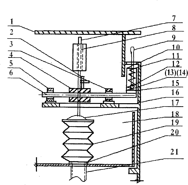
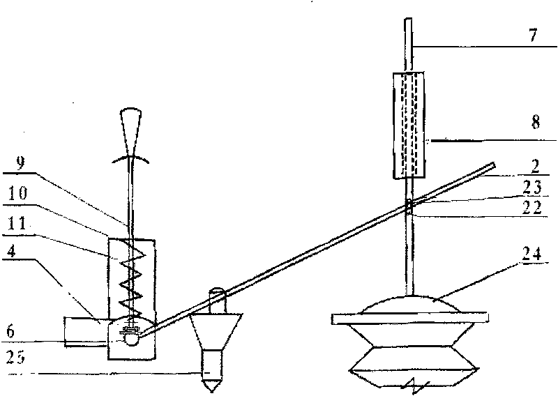
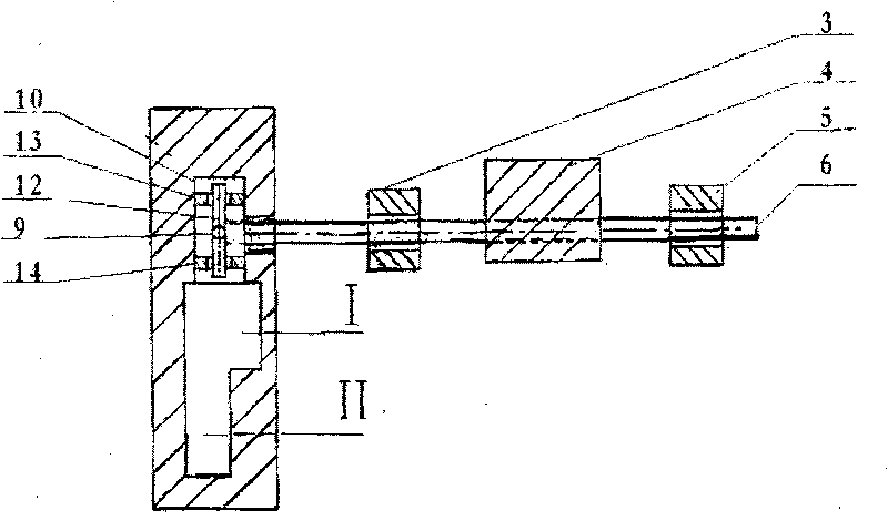
[0012] Example 1, see figure 1 , 2 , 3, at first process and make water storage tank (18), support (16), telescopic tube (19), the corresponding sealing of drainpipe (21) and the outlet (20) on the water storage pipe (18) is fixed, telescopic tube (19 ) lower port and the upper port of the drainpipe (21) are sealed and fixed, then the bracket (16) is fixedly installed on the tank wall of the water storage tank (18), and the sliding sleeve (8), axle seat (3 )(5), fix the upper counterweight (4) and the plate (15) on the shaft (6), fix the driving lever (2) on the counterweight (4), and then fix the driving lever (2) on the upper side belt The container (25) with drainage joints, the fixed position of the container with drainage joints on the side and the driving lever (2) should be determined according to the amount of flushing water required, and the balance time of the counterweight body (4) and the driving lever (2) should be determined. The shaft (6) is connected with the...

Embodiment 2

[0013] Embodiment 2, with embodiment 1, on the position of operating lever (9) on cabinet (1), process and make path I and path II, the upper surface of path I, II is arc-shaped, is conducive to observation and attractive in appearance like this. Water storage tank (18) can be installed on the cabinet frame of washbasin, and is corresponding with the outlet of washbasin, and will be close to the outlet of washbasin above, when washbasin cabinet was far away from closet, water storage tank ( 18) separately establish cabinet and install nearby, and be connected with the water tank below the washbasin with pipe, and the flushing port of drainpipe (21) other end introduces closet and is sealed and fixed.

[0014] According to the toilet flushing mechanism of the present invention, when in use, first, according to the amount of flushing water, one side force shaft (12) is used to rotate slightly, and the operating rod (9) touches the limit frame (10) and is pulled forward for operat...


PUM


Abstract

The invention discloses a toilet flushing mechanism which comprises a cabinet body (1) and a water storage tank (18) and is characterized in that a support (16) is arranged on and fixedly connected with the cabinet body (1); shaft seats (3) (5) and a sliding sleeve (8) are arranged on and fixedly connected with the support (16); a shaft (6) is connected with the shaft seats (3) (5) and is provided and fixed with a flat plate (15) and a counterweight body (4); shaft seats (13) (14) are arranged on and fixed with the flat plate (15); a shaft (12) is connected with the shaft seats (13) (14); an operating lever (9) is fixedly connected with the shaft (12); the bottom of an extension tube (19) is fixedly and hermetically connected with an upper port of a drain pipe (21); the upper part of the extension tube (19) is fixedly connected with a slide bar (7); the slide bar (7) is arranged in the sliding sleeve (8); and a shift lever (2) is fixedly connected with the counterweight body (4) and slantly leans against on a cross bar (22). The toilet flushing mechanism has reliability and long service life.

Description

(1) Technical field: [0001] The invention relates to the technical field of sanitary ware, in particular to a toilet flushing mechanism used on a toilet. (two) background technology: [0002] The toilet flushing mechanism of the closet used in toilet or toilet generally all is arranged in the closet water tank or the mode that is directly connected with running water pipe at present, and such mechanism has caused difficulty for the reasonable utilization of secondary water; The flushing valve mechanism is realized by the water blocking method that relies on the smooth and close contact of the two working surfaces, which requires extremely high water quality, and there are inevitably impurities in the water, which affects the reliability of the mechanism. With the enhancement of people's awareness of water saving , in life, people often use the used secondary water to flush the toilet, which is quite troublesome, time-consuming and inconvenient, especially for the elderly and...

Claims


Application Information

Patent Timeline
IPC IPC(8): E03D11/11E03C1/12
Inventor 张清玉
Owner 张清玉
Learn More