Shaver head

A razor and cutter head technology, applied in metal processing and other directions, can solve the problems of rising manufacturing cost, uneven force, affecting shaving effect, etc., and achieve the effect of low requirements, lower cost, and improved shaving effect

Inactive Publication Date: 2013-05-15
WENZHOU QINGDONG HARDWARE PRODS
View PDF0 Cites 0 Cited by
  • Summary
  • Abstract
  • Description
  • Claims
  • Application Information

AI Technical Summary

Problems solved by technology

[0002] The razor heads currently on the market generally include a ring body, a blade plastic frame and a net cover. The blade plastic frame is provided with a blade. Elastic mechanism, the blade is fixed on the blade plastic frame, and the blade relies on the elastic support provided by the blade plastic frame where it is located to push against the inner side of the net cover, but the force generated by the overall elastic rise of the blade plastic frame is generally not evenly distributed, so that each The force of the blade upward and sideways to tighten the top mesh cover is uneven, which will easily affect the shaving effect. The practice of some big brand razors is to improve the quality of the knife holder and the elastic support mechanism so that it can achieve balance as much as possible, but this It also increases the cost of manufacturing

Method used


Image

  • Shaver head
  • Shaver head
  • Shaver head

Examples


Embodiment Construction

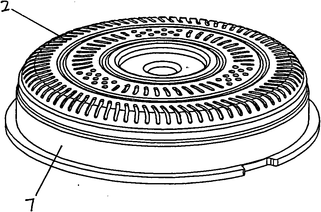
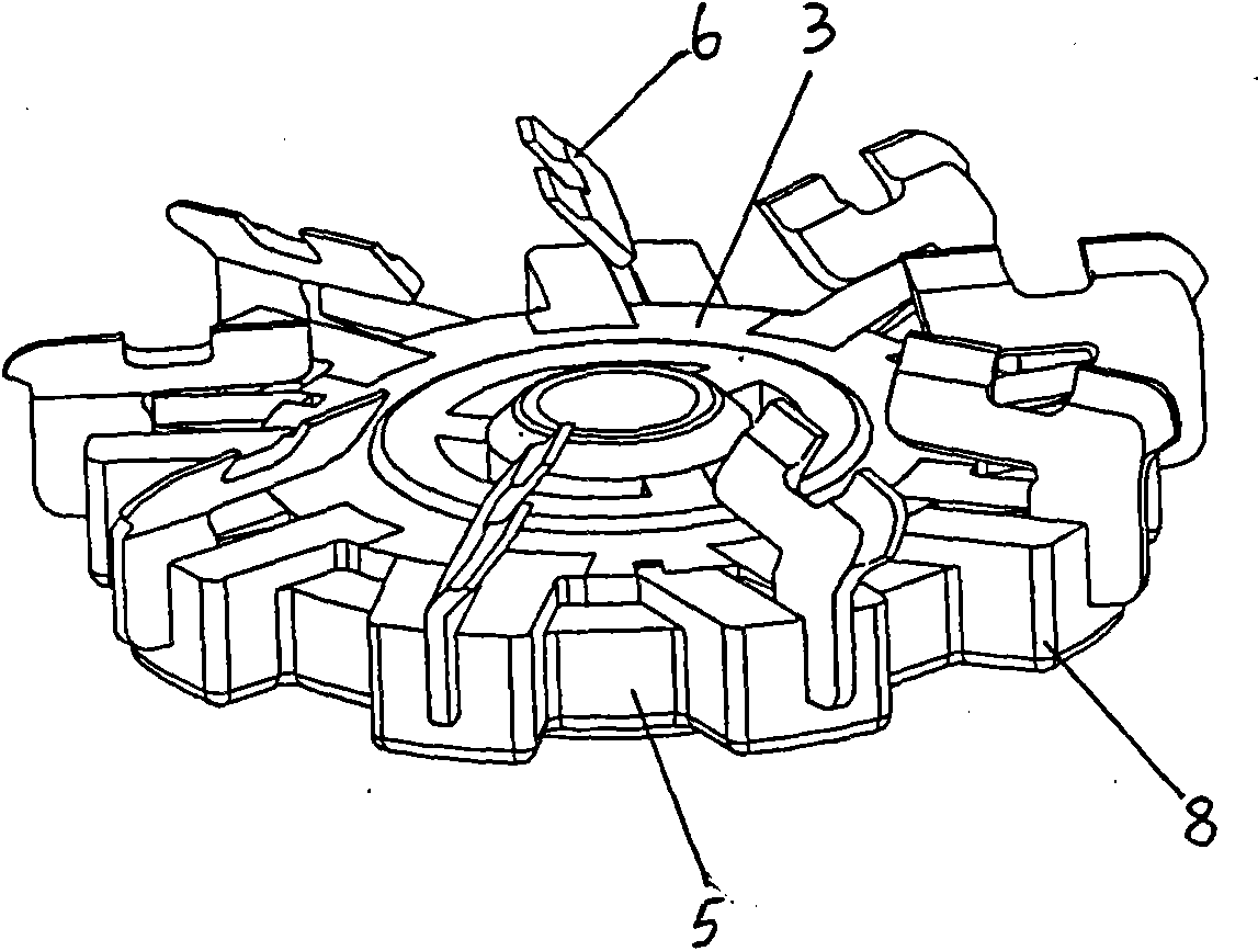
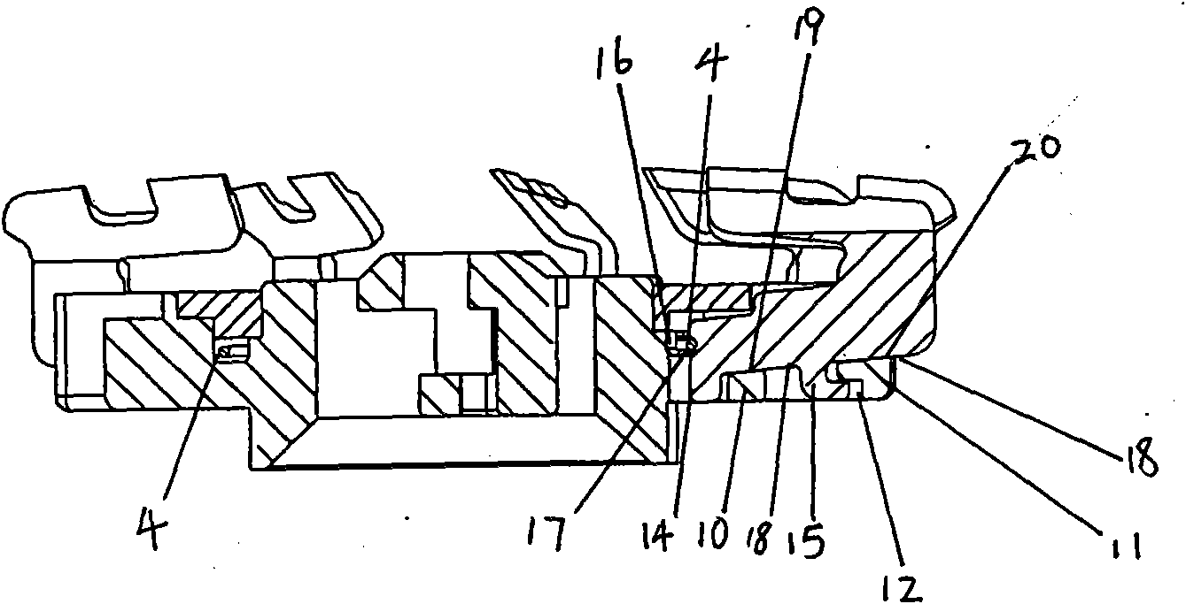
[0010] refer to figure 1 , figure 2 , image 3 , Figure 4 As shown, the first embodiment of the razor head provided by the present invention comprises a ring body 7, a plastic blade frame 5 and a net cover 2, the plastic blade frame 5 is provided with a blade 6, and the plastic blade frame 5 is arranged on the ring In the space formed by the body 7 and the net cover 2, the blade plastic frame 5 has a circularly distributed blade mounting seat 8, and the blade mounting seat 8 is provided with a mounting groove 9, and the mounting groove 9 has an upward and outward outlet. The inner bottom of the installation groove 9 is provided with a first block 10, the outer side of the bottom of the installation groove 9 is provided with a second block 11, the second block 11 is provided with a locking groove 12 inwardly, and the middle part of the blade 6 has an inner recess 13, The inner side of the lower end of the blade 6 has a first locking foot 14, and the middle part of the lowe...


PUM


Abstract

The invention discloses a shaver head. The shaver head comprises a blade plastic support; a blade is arranged on the blade plastic support; the blade plastic support is provided with an annually-distributed blade mounting seat; the blade mounting seat is provided with a mounting groove; the bottom of the inner side of the mounting groove is provided with a first clamping block; a second clamping block is arranged outside the mounting grove; the second clamping block is inwards provided with a clamping groove; a first clamping leg is arranged on the inner side of the lower end of a blade; the middle part of the lower end of the blade is provided with an L-shaped second clamping leg; the blade is inserted into the mounting groove; a space for the blade to move along the height direction andradial direction is reserved in the mounting groove, wherein the first clamping leg is clamped in the inner side of the first clamping block; the second clamping leg is clamped in the inner side of the second clamping block; the L-shaped end of the second clamping leg is inserted into the clamping groove; a spring positioning groove is formed on the inner side of the lower part of the blade; the blade plastic support is provided with an annular spring insertion groove on which a space for allowing a spring ring to perform radial elastic stretch is reserved; and the spring ring is arranged in the spring insertion groove and tightly supports against the spring positioning groove. As the force of each blade of the shaver head tightly supporting against a mesh enclosure is relatively uniform,the shaver head can effectively shave and reduce cost.

Description

technical field [0001] The present invention relates to a shaver head. Background technique [0002] The razor heads currently on the market generally include a ring body, a blade plastic frame and a net cover. The blade plastic frame is provided with a blade. Elastic mechanism, the blade is fixed on the blade plastic frame, and the blade relies on the elastic support provided by the blade plastic frame where it is located to push against the inner side of the net cover, but the force generated by the overall elastic rise of the blade plastic frame is generally not evenly distributed, so that each The force of the blade upward and sideways to tighten the top mesh cover is uneven, which will easily affect the shaving effect. The practice of some big brand razors is to improve the quality of the knife holder and the elastic support mechanism so that it can achieve balance as much as possible, but this It also increases the manufacturing cost. Contents of the invention [0...

Claims


Application Information

Patent Timeline
Patent Type & Authority Patents(China)
IPC IPC(8): B26B19/14
Inventor 潘庆平
Owner WENZHOU QINGDONG HARDWARE PRODS
Why Eureka
Try Eureka