
Electromagnetic relay with simple structure and strong shock resistance

An electromagnetic relay, a technology with a simple structure, applied in the directions of electromagnetic relays, electromagnetic relay details, relays, etc., can solve the problems of detachment, increase in freight cost, increase in manufacturing cost, etc., and achieve the effect of firm connection

Active Publication Date: 2010-07-14
XIAMEN HONGFA ELECTROACOUSTIC CO LTD
View PDF5 Cites 12 Cited by
  • Summary
  • Abstract
  • Description
  • Claims
  • Application Information

AI Technical Summary

Problems solved by technology

[0005] One is to sign a strict handling contract with the freight forwarding company; but this brings about an increase in freight costs;
[0006] The second is to use packaging with good handling buffer; but it brings about an increase in manufacturing costs;
With this design, it is easy to produce plastic chips due to the friction between the protrusion of the push card and the round hole of the moving spring during the operation of the relay, and, under severe impact, the instantaneous deformation of the moving spring may cause the protrusion of the push card to be rounded by the driven spring. jump out of the hole, so that the push card is separated from the movable spring; and the instantaneous opening and deformation of both sides of the push card may also cause the push card to be separated from the armature
Therefore, the impact resistance (especially the drop resistance) of products with this structure is relatively poor

Method used


Image

  • Electromagnetic relay with simple structure and strong shock resistance
  • Electromagnetic relay with simple structure and strong shock resistance
  • Electromagnetic relay with simple structure and strong shock resistance

Examples


Embodiment Construction

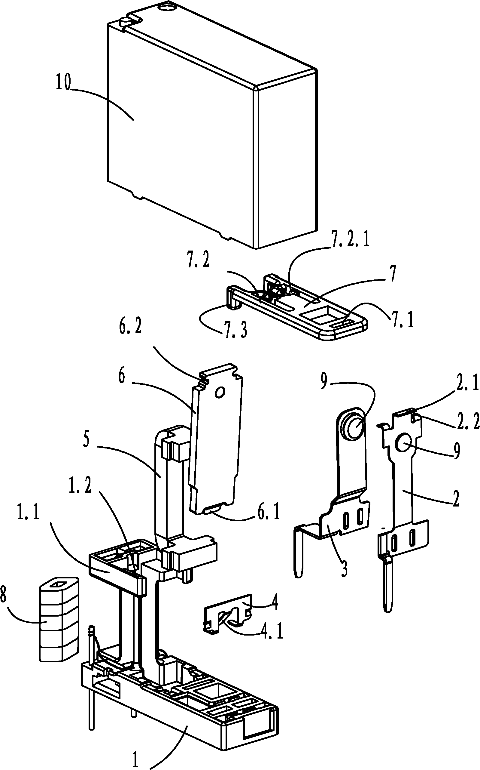
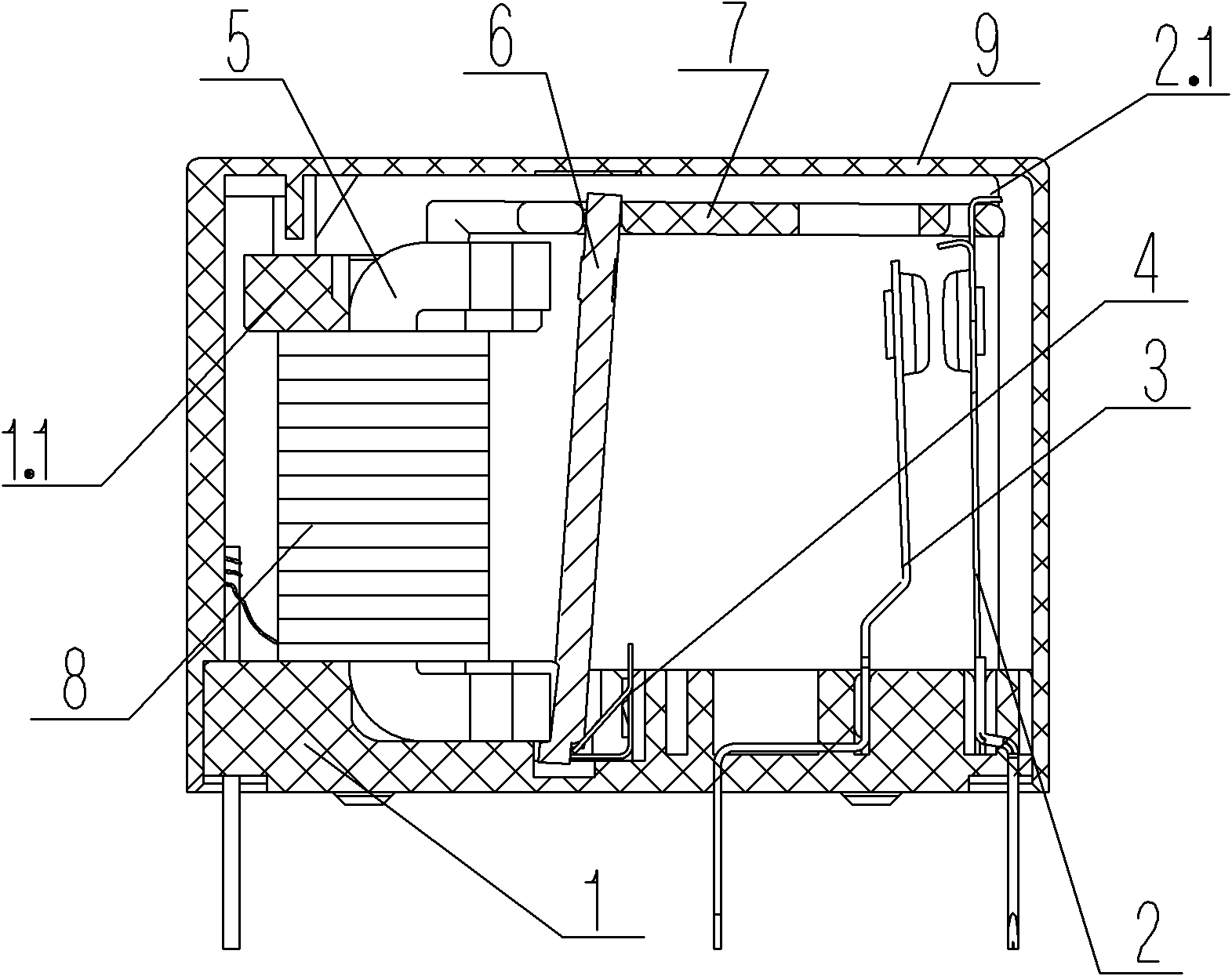
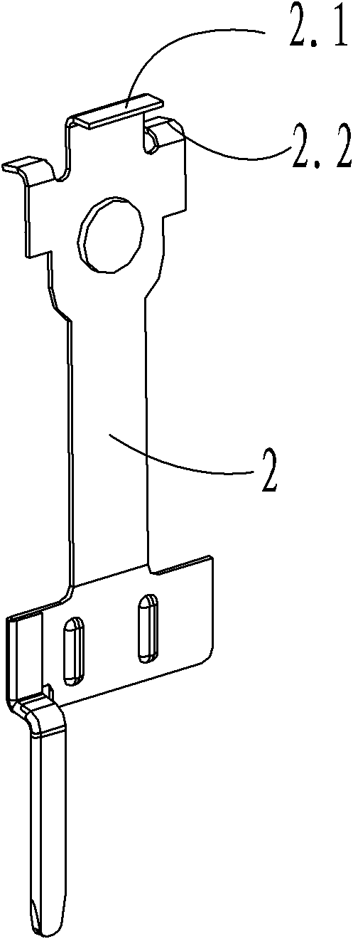
[0039] Examples, see Figure 1 to Figure 7 As shown, a kind of electromagnetic relay with simple structure and strong impact resistance of the present invention includes a base 1, a magnetic circuit part, a contact part, a push card 7 and a housing 10; On the base 1, the moving spring 2 is fixed with a contact 9 and is provided with a moving spring pin, and the static spring 3 is fixed with a contact 9 and is provided with a static spring pin; the magnetic circuit part includes a winding frame, an enameled wire 8, U-shaped iron core 5, armature 6 and compression spring 4; the extension 1.1 of the base constitutes a winding frame for winding enameled wire 8; enameled wire 8 is wound on the winding frame containing U-shaped iron core 5, that is, the extension 1.1 of the base Outside; one end of the armature 6 is fixed on the pole surface of one end of the iron core 5 by the compression spring 4, and the other end is used as a free end to connect with the second end of the push c...


PUM


Abstract

The invention discloses an electromagnetic relay with a simple structure and strong shock resistance, which comprises a base, a magnetic circuit part, a contact part and a pushing clip; one end of an armature iron props against a pole face on one end of an iron core, as a free end, the other end of the armature iron is in clamped connection with the second end of the pushing clip, and the first end of the pushing clip is connected with the free end of a movable spring; the free end of the movable spring is provided with a first hook-type structure which is arranged along the thickness direction of the movable spring and bends to one side; the first end of the pushing clip is provided with a mouth-shaped structure which can be matched with the first hook-type structure of the movable spring, and the opening size of the mouth-shaped structure to be matched with the thickness direction of the movable spring is set to be larger than the size of the thickness of the movable spring and smaller than the size of the bending section of the hook-type structure; and the first hook-type structure is arranged at the upper mouth edge of the mouth-shaped structure in a matching way. When the structure is used and the relay is assembled, the pushing clip can not break away from the matching movable spring and the matching armature iron under any drastic shock. Therefore, the structure has good shock resistance as well as good falling resistance.

Description

technical field [0001] The invention relates to an electromagnetic relay, in particular to an electromagnetic relay with simple structure and strong impact resistance. Background technique [0002] At present, with the improvement of people's living standards, the application of household appliances such as color TVs, air conditioners, refrigerators, washing machines, water heaters, soybean milk machines, etc. is becoming more and more common, and there is a tendency to gradually spread to small towns and rural areas; in North America, Western Europe, etc. In developed countries abroad, in addition to the above-mentioned general-purpose household appliances, high-end household appliances such as automatic dishwashers, electric heating carpets, and electronic massagers have basically entered ordinary households. [0003] As the basic control element of household appliances, the electromagnetic relay's market application field is also expanding with the continuous updating of ...

Claims


Application Information

Patent Timeline
Patent Type & Authority Applications(China)
IPC IPC(8): H01H50/16H01H50/64H01H49/00
Inventor 刘金枪
Owner XIAMEN HONGFA ELECTROACOUSTIC CO LTD
Learn More