
Lifesaving device

A life-saving device and deceleration device technology, applied in life-saving equipment, building rescue, etc., can solve the problems of automatic control of the descending speed, difficulty in use, manual adjustment, etc., and achieve the effect of simple structure, small space occupation, and installation-free

Inactive Publication Date: 2011-06-08
李贤
View PDF0 Cites 0 Cited by
  • Summary
  • Abstract
  • Description
  • Claims
  • Application Information

AI Technical Summary

Problems solved by technology

[0002] At present, there are some life-saving products for high-rise buildings on the market. Their structures are complex. In addition to the main working devices, there are more auxiliary equipment that need to be installed; some descending speeds cannot be automatically controlled and need to be adjusted manually; Inconvenient factors such as limited quantity; it will be difficult to use in special environments or special personnel

Method used


Image

  • Lifesaving device
  • Lifesaving device
  • Lifesaving device

Examples


Embodiment Construction

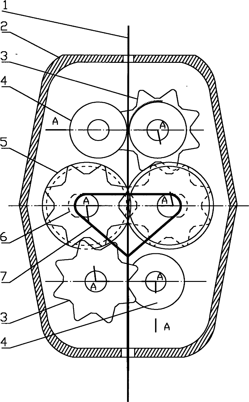
[0015] Such as figure 1 A specific embodiment is shown, which includes a guide belt 1, a housing 2, a main deceleration device 3, an auxiliary deceleration device 4, a speed measuring mechanism 5 and a suspension belt 7. The main deceleration device 3 , the auxiliary deceleration device 4 and the speed-measuring mechanism 5 each have two sets, and the main deceleration device 3 , the auxiliary deceleration device 4 and the speed-measuring mechanism 5 are all arranged in the housing 2 .

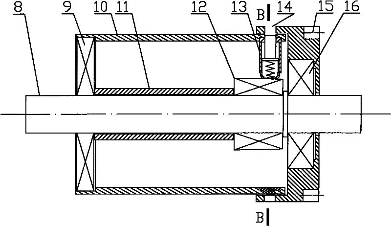
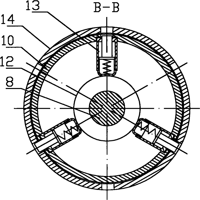
[0016] Such as figure 2 and image 3 As shown, the speed measuring mechanism 5 includes a support rod 8, a bearing I 9, a friction housing 10, a support housing 11, a bearing II 12, a centrifugal speed measuring device 13, a speed measuring gear 15 and a bearing III 16, and the support housing 11 is sleeved on the support rod 8, the bearing I 9 is installed on the support rod 8 and is located on one side of the support housing 11, the bearing II 12 is installed on the support rod 8 and is l...


PUM


Abstract

The invention discloses a lifesaving device, comprising a guide belt, a housing, a speed measuring mechanism and a speed reducing mechanism; the housing is sheathed on the guide belt; the speed measuring mechanism and the speed reducing mechanism are installed on the housing; the speed measuring mechanism comprises a speed measuring gear and a rubbed housing contacted with the guide belt in rolling manner; the speed reducing mechanism comprises a speed reducing housing having a gradually changed friction factor with the guide belt during the rotating process and a speed reducing gear for driving the speed reducing housing to rotate; the speed measuring gear is engaged with the speed reducing gear; a centrifugal speed measuring device which can be connected with the rubbed housing and speed measuring gear to drive the speed measuring gear to rotate is installed on the rubbed housing when the rotation speed of the rubbed housing reaches a pre-set value. The lifesaving device can effectively control the descending speed of the heavy article to prevent the heavy article from being descended fast. The lifesaving device is suitable for saving life on high buildings, and is capable of preventing people from being descended fast; and the lifesaving device with simple and compact structure takes small space and does not need to assemble.

Description

technical field [0001] The invention relates to a life-saving device, in particular to a life-saving device capable of controlling the falling speed of an object when falling from a certain height. Background technique [0002] At present, there are some life-saving products for high-rise buildings on the market. Their structures are complex. In addition to the main working devices, there are more auxiliary equipment that need to be installed; some descending speeds cannot be automatically controlled and need to be adjusted manually; There are restrictions on the quantity and other factors that are inconvenient to use; it will be difficult to use it in a special environment or by a special person. Contents of the invention [0003] In order to solve the above technical problems, the present invention provides a lifesaving device that can automatically control the maximum descending speed of an object. [0004] In order to solve the above-mentioned technical problems, the ...

Claims


Application Information

Patent Timeline
Patent Type & Authority Patents(China)
IPC IPC(8): A62B1/06
Inventor 史越华李贤
Owner 李贤
Learn More