
Necessity automatic speed control lifting device

A lifting device and emergency avoidance technology, applied in life-saving equipment, building rescue, etc., can solve problems such as loss of balance, easy to panic, unsafe, etc., and achieve the effect of simple and practical structure, good economic benefits, and simple operation

Inactive Publication Date: 2011-12-21
XIANGTAN UNIV
View PDF3 Cites 0 Cited by
  • Summary
  • Abstract
  • Description
  • Claims
  • Application Information

AI Technical Summary

Problems solved by technology

I think there are several defects in this patent: First, the device is fixed on the wall, such as the inner wall, which is not only unsightly, but also may cause people to fall down. If it is on the outer wall, it also provides convenience for criminals. Moreover, the materials used are exposed to the sun and rain, and the temperature changes in the four seasons, which reduces the durability and reliability; second, the horizontal bar is very unsafe and easy to lose balance. For the old, weak, sick and disabled, a man-carrying bag can be hung on the horizontal bar. For the old, weak, sick and disabled, I think life-saving devices should be in place in one step. In addition, the old, weak, sick and disabled cannot enter the outer horizontal bar by themselves. in the man-carrying bag; thirdly, the structure of the life-saving device is complex and the manufacturing cost is high

Method used


Image

  • Necessity automatic speed control lifting device
  • Necessity automatic speed control lifting device
  • Necessity automatic speed control lifting device

Examples


Embodiment Construction

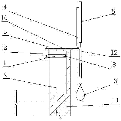
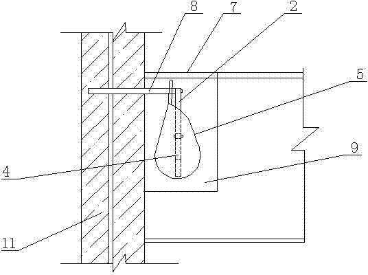
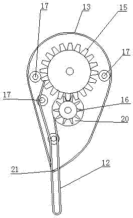
[0028] by attached figure 1 , figure 2 , image 3 , Figure 4 As shown, an emergency avoidance self-controlled speed lifting device is characterized in that it includes a force arm 8, most of which are fixed in a reinforced concrete column 11, a small part is suspended in a wall cabinet 9, a force arm 8, a telescopic arm I1 , telescopic arm II2, telescopic arm III3, and telescopic arm IV4 are hinged sequentially, and telescopic arm IV4 is fixedly equipped with rope box 5; The journal at the end is respectively connected with the upper box body 14 and the lower box body 13 through the bearing 22, a large gear 15 is arranged on one side of the runner 18, and a pinion 16 is arranged on the same side of the rotating shaft 19 relative to the runner 18, and the gearwheel 15 has a large number of teeth. The pinion gears 16 mesh with each other and have the same modulus. A baffle plate 20 is set inside the pinion gear 16. A movement gap is set between the outer circular surface of...


PUM


Abstract

The invention discloses a necessity automatic speed control lifting device. The invention adopts a technical scheme that: most of a stress arm is fixed in a reinforced concrete column, and a small part of the stress arm is suspended in a wall cabinet; the stress arm, a telescopic arm I, a telescopic arm II, a telescopic arm III and a telescopic arm IV are hinged in turn, and a rope belt box is fixedly arranged on the telescopic arm IV; the rope belt box comprises an upper box body and a lower box body which are connected through a bolt; shaft necks at two ends of a rotating wheel and a rotating shaft are connected with the upper box body and the lower box body respectively through bearings; a gearwheel is arranged on the same side of the rotating wheel; a pinion is arranged on one side ofthe rotating shaft; a baffle is arranged on an inner side of the pinion; a movement gap is formed between an excircle surface of the baffle and an excircle surface of the rotating wheel; two ends of the rope belt are wound on the excircle surfaces of the rotating wheel and the rotating shaft in the same direction; the rope belt is extended out of a box opening on the lower part of the rope belt box through a plurality of guiding shafts; and the plurality of guiding shafts are connected with the upper box body and the lower box body respectively through bearings. Therefore, the defect that theconvenient necessity equipment is absent in high-rise buildings is overcome. The necessity automatic speed control lifting device is applied to household high-rise flats, public office buildings, classroom buildings, and the like.

Description

technical field [0001] The invention relates to an emergency avoidance in the high-rise building industry, in particular to an emergency avoidance self-controlled speed lifting device for emergency avoidance of high-rise residential households, public office buildings, and teaching buildings. Background technique [0002] The 5.12 Wenchuan Earthquake was a disastrous and sad day for the Chinese people. The collapse and damage of buildings caused great casualties to the affected people. Although the disaster is terrible, as long as we are prepared to deal with it, we can avoid the loss of personnel during the disaster. Casualties, or minimize the loss of the disaster. At present, multi-storey buildings and various office buildings and office buildings are not designed with special escape devices. Especially in the event of a fire, the trapped people cannot escape from the door, the elevator cannot be used, and the corridors are full of toxic smoke. The simple way to escape i...

Claims


Application Information

Patent Timeline
Patent Type & Authority Patents(China)
IPC IPC(8): A62B1/06
Inventor 谭红霞杨裕恒范志甫涂莉
Owner XIANGTAN UNIV
Learn More