
Double-pole isolating switch cabinet for outdoor direct current 1500 V contact net system

A technology of isolating switch and catenary, which is applied in substation/switch layout details, substation/switchgear cooling/ventilation, substation/distribution device casing, etc., which can solve problems such as electrical short circuit, component burnout, and high humidity. To achieve the effect of convenient fixing and connection, safe maintenance and small size

Inactive Publication Date: 2010-08-04
成都通力集团股份有限公司
View PDF0 Cites 6 Cited by
  • Summary
  • Abstract
  • Description
  • Claims
  • Application Information

AI Technical Summary

Problems solved by technology

[0002] The urban subway is equipped with a DC 1500V catenary system. Due to the existence of ultra-high DC voltage, the circuit breaking and closing of the catenary system will generate huge heat instantaneously in the switchgear. If effective measures are not taken in time to remove the heat, the switchgear will be affected. The normal operation of the internal components will cause the components to burn out in severe cases, thereby shortening the service life of the switchgear
[0003] In addition, in the humid season, the humidity in the air is high, and under the action of ultra-high direct current, it will cause electrical short circuit, which is not conducive to the safe operation of equipment.

Method used


Image

  • Double-pole isolating switch cabinet for outdoor direct current 1500 V contact net system
  • Double-pole isolating switch cabinet for outdoor direct current 1500 V contact net system
  • Double-pole isolating switch cabinet for outdoor direct current 1500 V contact net system

Examples


Embodiment Construction

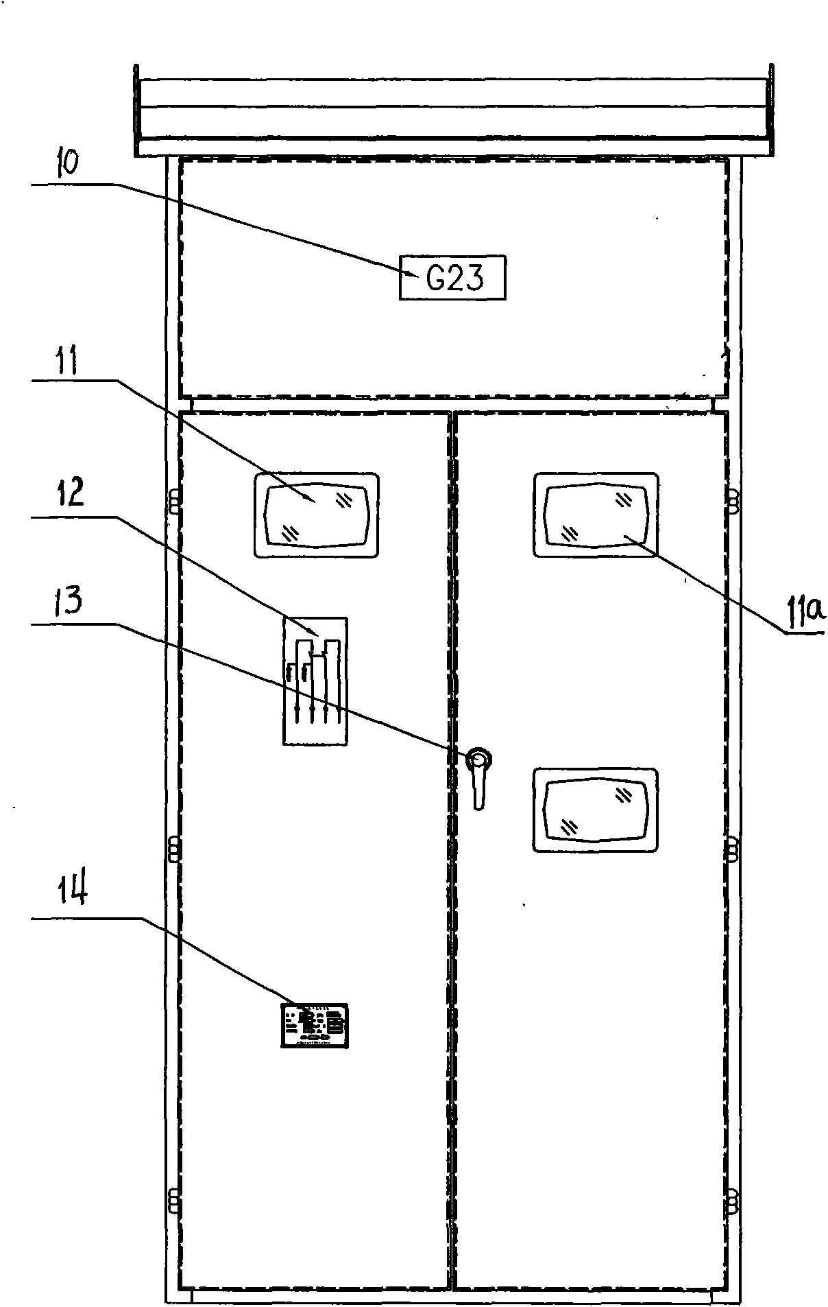
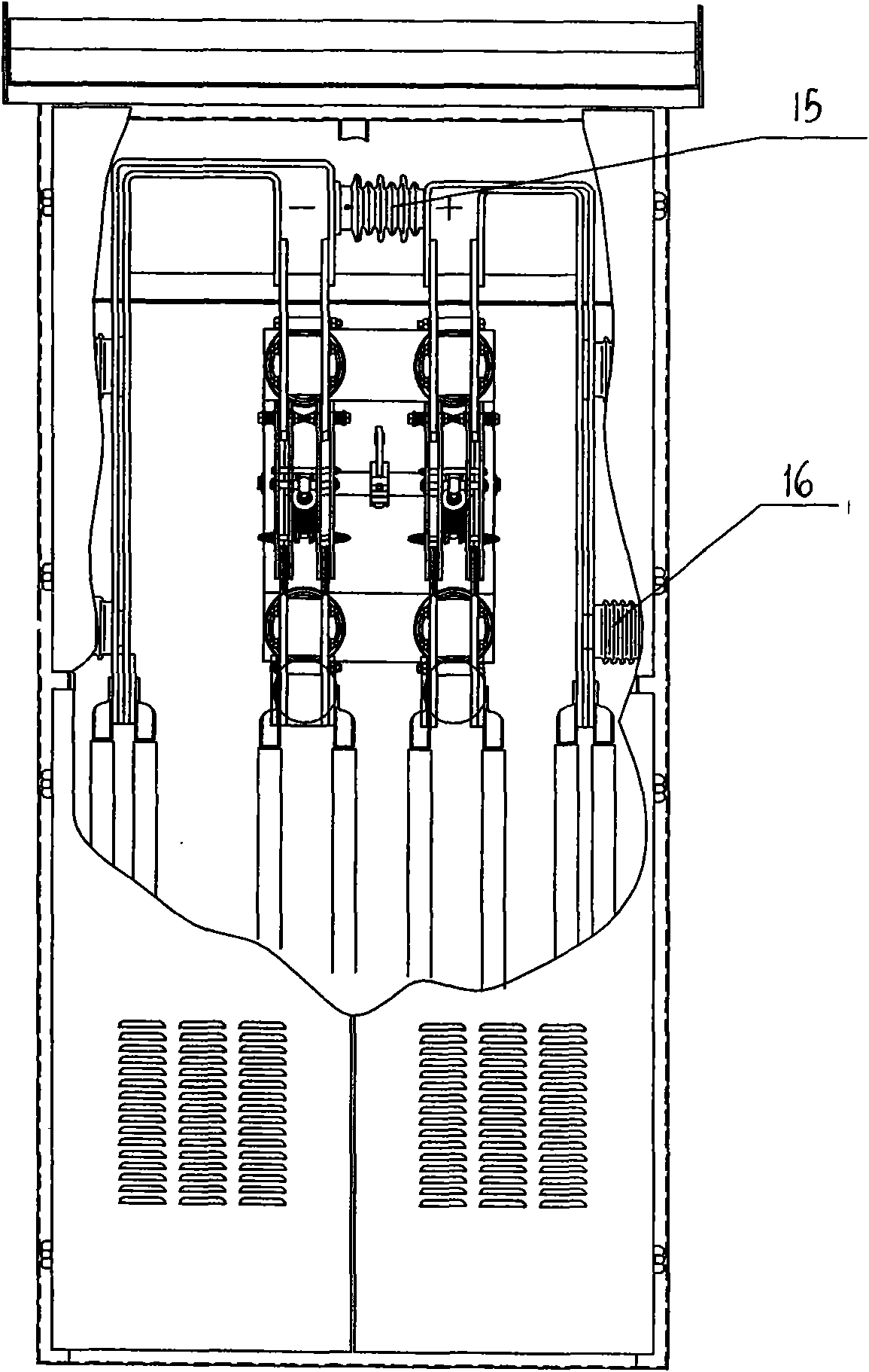
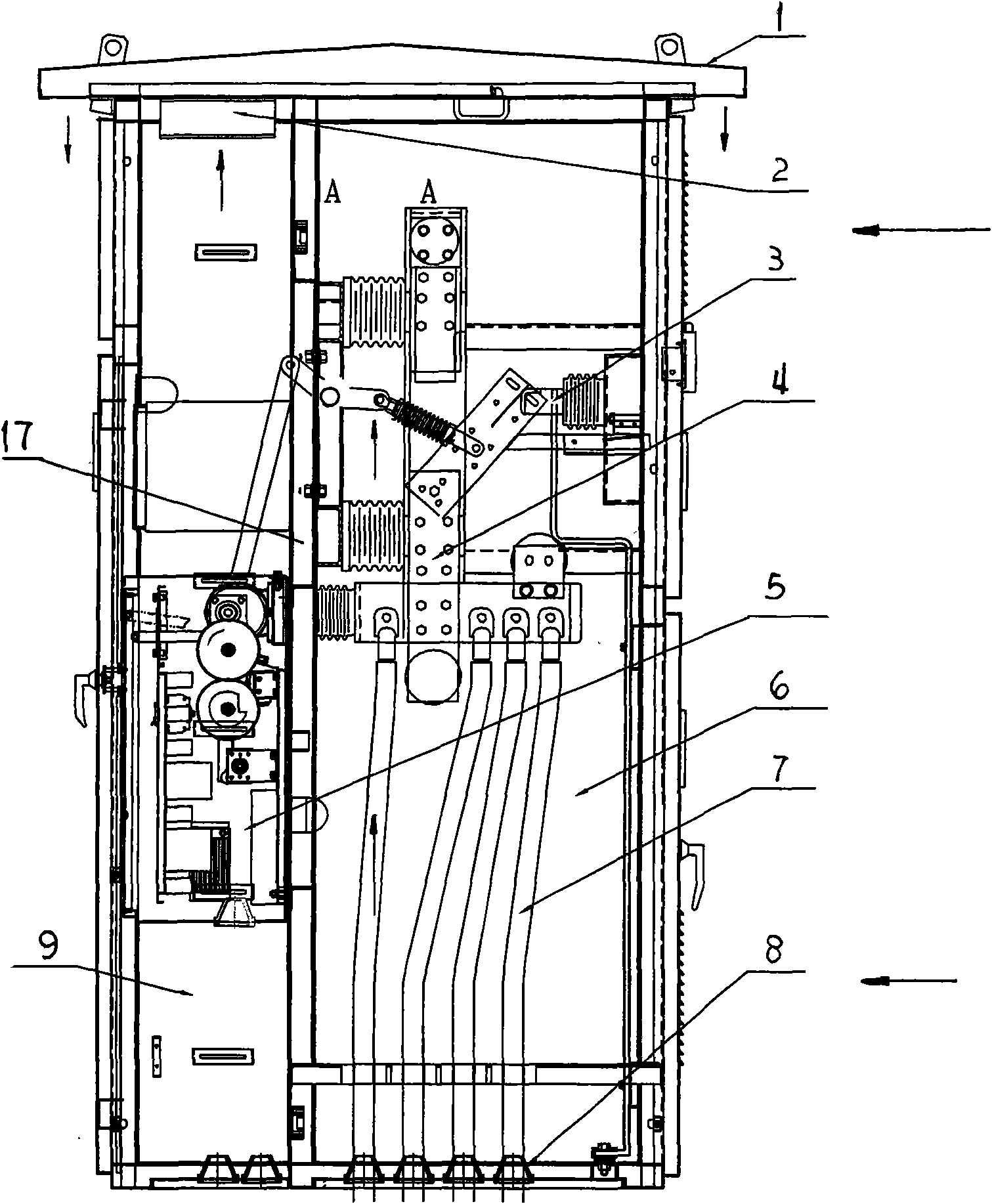
[0022] Figure 5 As shown, the present invention comprises a cabinet body, a primary cable 7, a DC bipolar isolating switch 4, an electric operating system 5, and a longitudinal partition 17 is arranged in the cabinet, and the longitudinal partition divides the cabinet cavity into an anterior chamber and a rear chamber, and the rear chamber The horizontal partition 18 installed in the room divides the back room into the rear upper room and the rear lower room; the electric operating mechanism 5 is installed in the front room; the DC bipolar isolating switch 4 is installed in the rear upper room; the primary cable 7 is installed in the rear lower room; The cabinet is also provided with a shell-type rainproof ceiling 1, and the heat dissipation fan 2 is installed on the rainproof ceiling 1. The air outlet of the heat dissipation fan is connected with the air inlet of the rainproof ceiling, and multiple air outlets of the rainproof ceiling are arranged on On the surrounding eaves...


PUM


Abstract

The invention relates to a double-pole isolating switch cabinet for an outdoor direct-current 1500 V contact net system, which belongs to a high-power direct-current double-pole isolating switch cabinet used for subways or urban light rail systems. The cavity of the cabinet body is separated into a front chamber, an upper back chamber and a lower back chamber through a longitudinal baffle and a horizontal baffle; an electric operating mechanism is arranged in the front chamber; the direct-current double-pole isolating switch is installed in the upper back chamber; a primary cable is arranged in the lower back chamber; a shell-type rain-proof ceiling is installed on the cabinet, a heat radiating blower is installed on the rain-proof ceiling, an air outlet of the heat radiating blower is connected with an air inlet of the rain-proof ceiling, periphery eaves of the rain-proof ceiling is provided with a plurality of air outlets, doors of the upper back chamber and the lower back chamber are both provided with air inlet shutters, and the upper part of the vertical baffle and the horizontal baffle are both provided with air vents; and the lower back chamber is also provided with an electric heater. A back door is provided with an electromagnetic lock provided with electric interlocking control. The invention not only can radiate heat, ventilate the cabinet and exhaust air, but also can prevent condensation and satisfy the usage requirement of outdoor environment.

Description

technical field [0001] The invention relates to a switchgear for power distribution, in particular to an outdoor DC 1500V catenary bipolar isolating switchgear for urban subways or light rails. Background technique [0002] The urban subway is equipped with a DC 1500V catenary system. Due to the existence of ultra-high DC voltage, the circuit breaking and closing of the catenary system will generate huge heat instantaneously in the switchgear. If effective measures are not taken in time to remove the heat, the switchgear will be affected. The normal operation of the internal components will cause the components to burn out in severe cases, thereby shortening the service life of the switchgear. [0003] In addition, in the humid season, the humidity in the air is high, and under the action of ultra-high direct current, it will cause electrical short circuit, which is not conducive to the safe operation of equipment. Contents of the invention [0004] The object of the pres...

Claims


Application Information

Patent Timeline
Patent Type & Authority Applications(China)
IPC IPC(8): H02B1/00H02B1/30H02B1/56
Inventor 周元开赵新
Owner 成都通力集团股份有限公司
Learn More