

Liquid-crystalline medium
A liquid crystal medium and medium technology, applied in liquid crystal materials, chemical instruments and methods, etc., can solve problems such as burning and image retention
- Summary
- Abstract
- Description
- Claims
- Application Information
AI Technical Summary
Problems solved by technology
Method used
Image

Examples
Embodiment approach
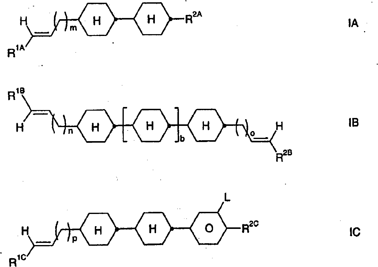
[0040] a) R in formula IA, IB and IC 1A , R 1B , R 2B and R 1C preferably represents a straight-chain alkyl group, especially C 2 h 5 , n-C 3 h 7 , n-C 4 h 9 , and n-C 5 h 11 , n-C 6 h 13 .
[0041] R 2A and R 2C Preferably represents alkyl or alkoxy, especially CH 3 , n-C 3 h 7 , n-C 5 h 11 , and C 2 h 5 , n-C 4 h 9 .
[0042] The alkenyl side chains in the compounds of formulas IA, IB and IC are preferably present in the E configuration.
[0043] b) Liquid-crystalline media comprising one, two, three, four or more, preferably one, two or three compounds of the formulas IA, IB and / or IC.
[0044] c) Liquid-crystalline media in which the proportion of the compound of the formula IA in the total mixture is ≧5% by weight, preferably at least 10% by weight, particularly preferably ≧15% by weight.
[0045] If present, the proportion of compounds of the formula IB in the overall mixture is preferably ≧5% by weight, in particular ≧10% by weight, very partic...
Embodiment 1
[0276] CY-3-O4 9,60% Clearing point [°C]: 63
[0277] CY-5-O4 9,60% Δn[589nm, 20°C]: 0,0762
[0278] CCY-2-O2 9,60% Δε[1kHz, 20°C]: -3,0
[0279] CCY-3-O2 9,60% 1 [mPa·s, 20°C]: 112
[0280] CCY-5-O2 6,40%
[0281] CCY-2-1 9,60%
[0282] CCY-3-1 6,40%
[0283] CC-5-V 6,40%
[0284] PCH-53 12,80%
[0285] CC-1-V3 20,00%
Embodiment 2
[0287] CY-3-O4 9,60% Clearing point [°C]: 78
[0288] CY-5-O4 9,60% Δn[589nm, 20°C]: 0,0820
[0289] CCY-2-O2 9,60% Δε[1kHz, 20°C]: -3,1
[0290] CCY-3-O2 9,60% 1 [mPa·s, 20°C]: 140
[0291] CCY-5-O2 6,40%
[0292] CCY-2-1 9,60%
[0293] CCY-3-1 6,40%
[0294] CC-5-V 6,40%
[0295] PCH-53 12,80%
[0296] CC-5-V3 20,00%
PUM
 Abstract
Description
Claims
Application Information