
Intramedullary rod instrument

An intramedullary rod and instrument technology, applied in the field of surgical instruments, can solve the problems of small space availability and difficulty in ensuring selection, etc.

Active Publication Date: 2010-08-11
DUPUY INT LTD
View PDF0 Cites 12 Cited by
  • Summary
  • Abstract
  • Description
  • Claims
  • Application Information

AI Technical Summary

Problems solved by technology

Also, due to the configuration of the pivot mechanism, there is very little space available for the different optional angles, and therefore it may be difficult to ensure that the correct angle is selected

Method used


Image

  • Intramedullary rod instrument
  • Intramedullary rod instrument
  • Intramedullary rod instrument

Examples


Embodiment Construction

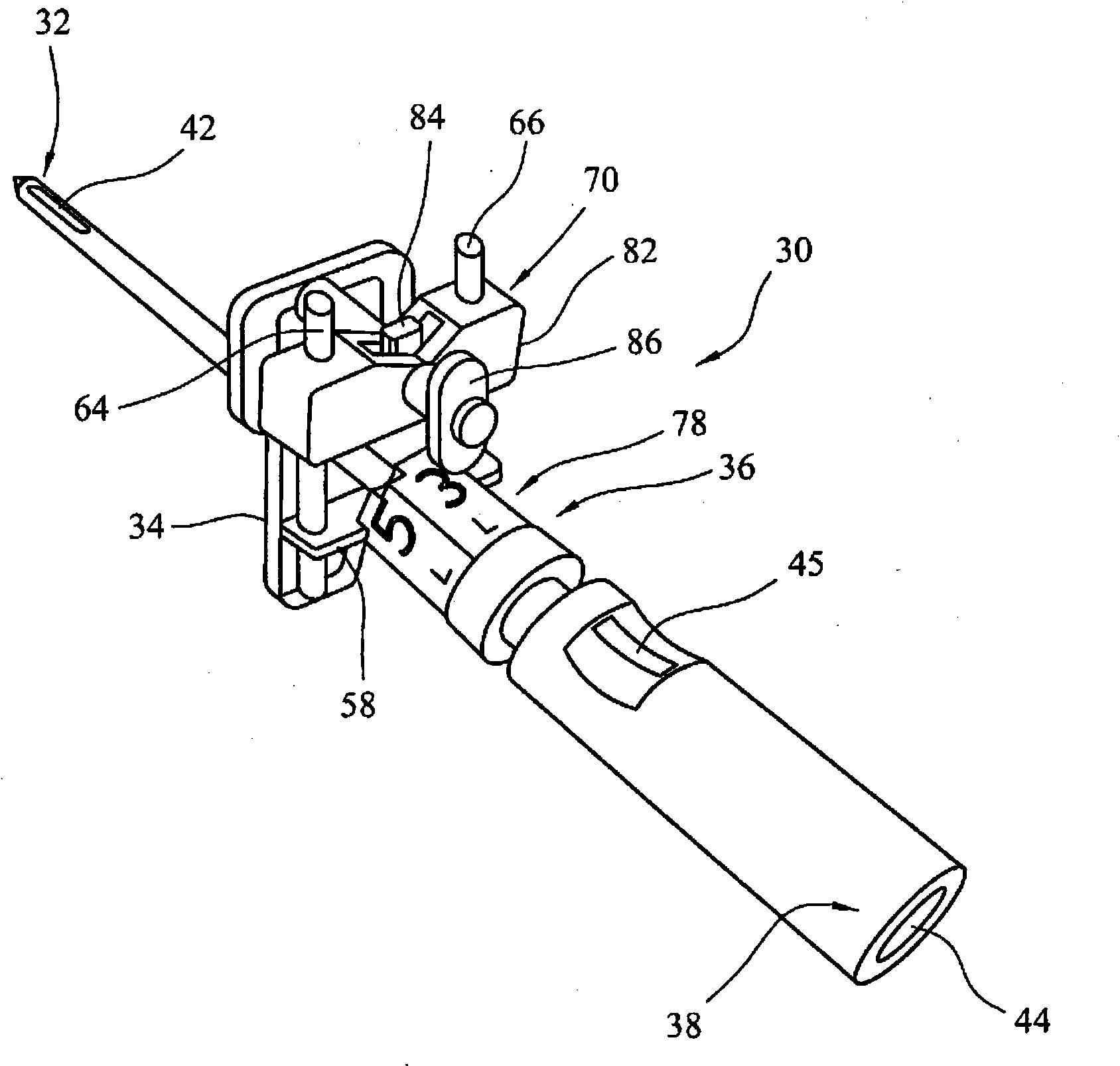
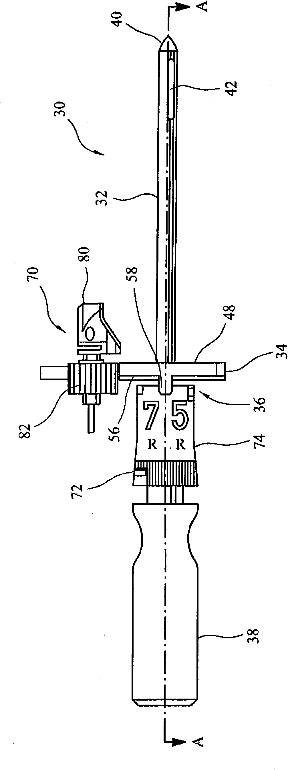
[0040] figure 2 A perspective view of the instrument 30 according to the invention is shown. image 3 A side view of the instrument 30 is shown, Figure 4 For along image 3 The line AA goes through the cross-sectional view of the instrument, Figure 5 Is the end view of the instrument from the handle end and Image 6 The view from the top of the instrument. Figure 7 Shows an enlarged cross-sectional view including the tip of the instrument along line AA, showing the centralizer mechanism, and Figure 8 with 9 It is a perspective view of the centralizer mechanism. Picture 10 with 11 To show a perspective view of the centralizer mechanism in use.

[0041] The instrument 30 includes an intramedullary (IM) rod 32, a main body 34, an angle adjustment mechanism 36, and a handle 38.

[0042] The rod 32 has a generally tubular configuration and includes a tip 40 at its free end. Three holes 42 are provided to the free end of the rod. Three fin pieces 102, 104, 106 are provided in the ro...


PUM


Abstract

A femoral instrument (30) for use in the intramedullary canal is described and includes an intramedullary (32) rod having a tip (40) at a free end. A body (34) is attached to the intramedullary rod and has a face (48) with a bone abutting portion. A centraliser mechanism is located within the rod and is operable to deploy and retract a plurality of members (102, 104, 105) to engage and disengage an inner surface of the intramedullary canal. The length of the intramedullary rod from the tip to the face of the body is less than 30cm. The instrument can also include an angular adjustment mechanism (36). The angular adjustment mechanism can have a plurality of formations (60, 62) and can be rotated about the longitudinal axis of the intramedullary rod to present at least a one of the formations to abut a portion of the body to define the relative angle between the body and the intramedullary rod.

Description

Technical field [0001] The present invention relates to a surgical instrument, and more particularly to a surgical instrument including an intramedullary rod. Background technique [0002] Intramedullary rods can be used in knee arthroplasty to provide a reference to which a cutting guide or block can be attached to perform femoral cutting. It should be appreciated that the present invention relates to an intramedullary rod that provides references or some other features or elements used during bone preparation, rather than a type of rod that is placed in the intramedullary cavity (intramedullary canal) inside and fastened with bone screws or the like for repairing broken bone or for other types of damage applications. [0003] Intramedullary rods are typically about 40 cm, or as long from the tip of the rod to the bone engaging structure that engages the bone surface in use. The end of the rod of this length is fastened in the medullary cavity and therefore self-positions. Howe...

Claims


Application Information

Patent Timeline
Patent Type & Authority Applications(China)
IPC IPC(8): A61B17/15
CPCA61B17/7266A61B17/155A61B17/157A61B17/154A61B17/15
Inventor M·克克曼L·斯特劳克斯A·费尔特拉莫J·奈布尔
Owner DUPUY INT LTD
Learn More