Intramedullary Rod for Assisting Total Knee Joint Replacing Operation and Method for Controle Operation Using the Rod

a technology of intramedullary rods and rods, which is applied in the field of intramedullary rods, can solve the problems of reducing the cleaning time of surgical instruments, affecting the cleaning effect of surgical instruments, so as to reduce the cleaning time, and accurately recognize the direction of rods

Inactive Publication Date: 2011-03-24
NLLGATA TLO LNC
View PDF9 Cites 42 Cited by
  • Summary
  • Abstract
  • Description
  • Claims
  • Application Information

AI Technical Summary

Benefits of technology

According to the present invention, it becomes possible to accurately recognize the direction of a rod from a narrow field of vision for fluoroscopy, by using the special bone cutting positioning jig employing the intra-medullary rod. The coordinate system (exclusive of rotation) of the intra-medullary rod is determined by digitizing, with help of the intra-medullary rod of the present invention, both ends of the intra-medullary rod with the C-arm fluoroscopic image during the operation. Next, by digitizing the intersection of steel wires buried in the cylindrical body made of a X-ray transmitti

Problems solved by technology

(1) Estimation of resected bone surface with the intra-medullary rod was possible only in the abduction and adduction directions. Meanwhile, since the estimation was not possible in its rotation and bending directions, a bone cutting device corresponding to each had to be attached and each direction was determined by observation with the naked eye. However, this method made it difficult to determine a precise direction of the resected bone surface, and the surgical instrument has been getting bulky.
(2) The operation assistance using an optic

Method used


Image

  • Intramedullary Rod for Assisting Total Knee Joint Replacing Operation and Method for Controle Operation Using the Rod
  • Intramedullary Rod for Assisting Total Knee Joint Replacing Operation and Method for Controle Operation Using the Rod
  • Intramedullary Rod for Assisting Total Knee Joint Replacing Operation and Method for Controle Operation Using the Rod

Examples


Embodiment Construction

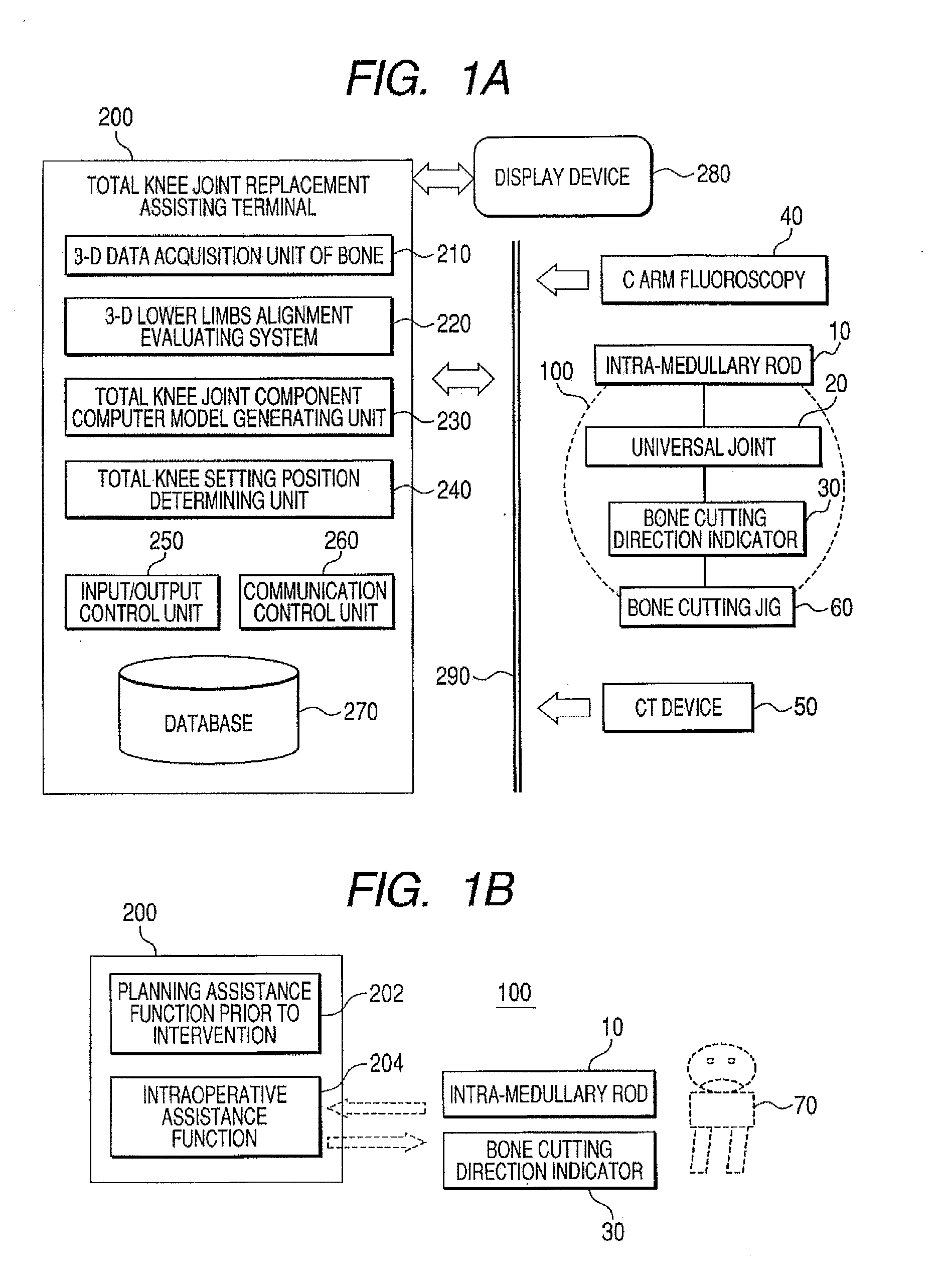
Referring to FIG. 1, the following will now explain a bone cutting positioning jig and a system for assisting a total knee joint replacement using the same, in accordance with one embodiment of the present invention. As shown in a configuration of the system in FIG. 1A, the system for assisting a total knee joint replacement of the present invention includes a bone cutting positioning jig 100 and a total knee joint replacement assisting terminal 200.

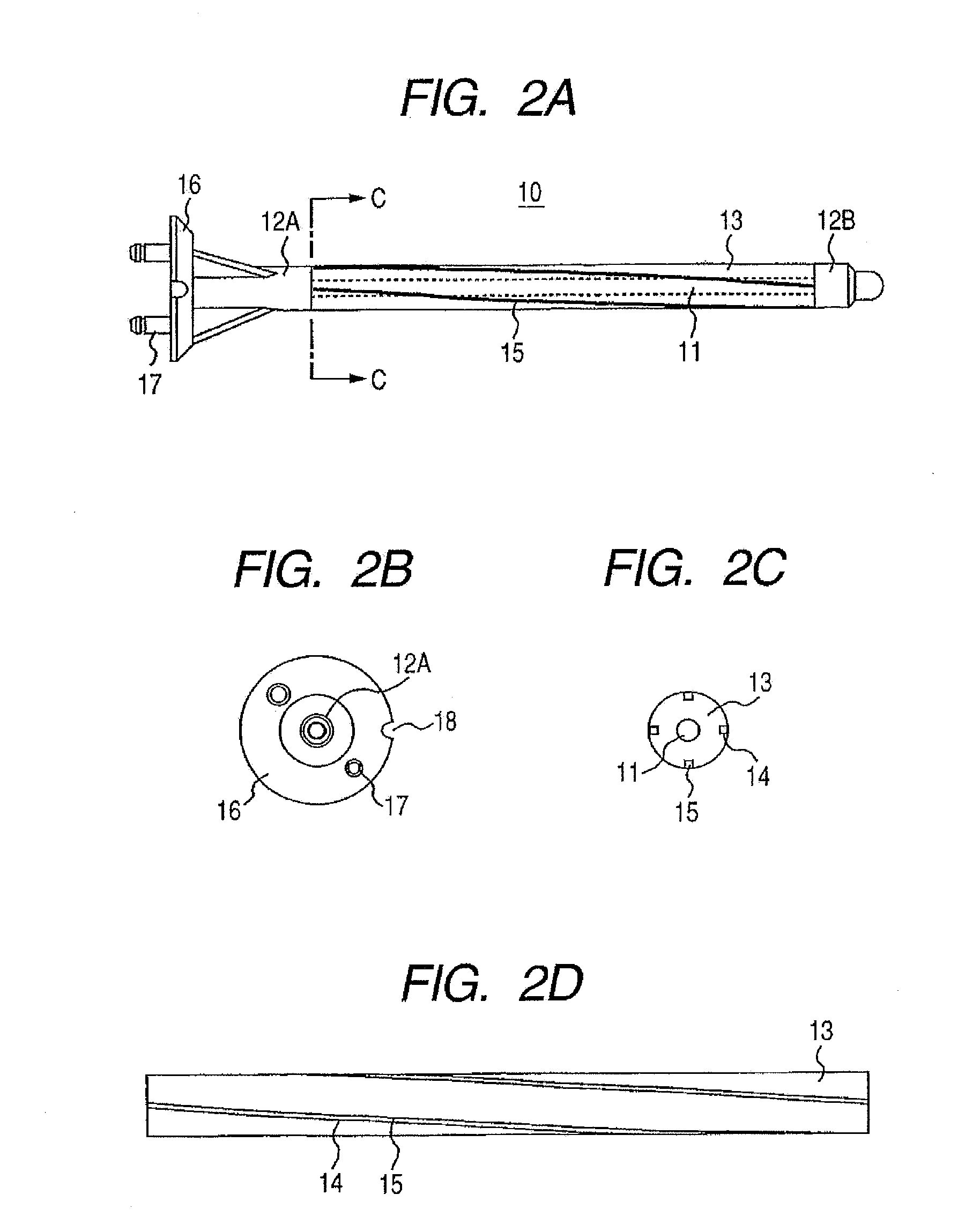
First, the bone cutting positioning jig 100 includes an intra-medullary rod 10, and a bone cutting direction indicator 30 connected to the intra-medullary rod via a universal joint 20. A bone cutting jig 60 is mounted on the bone cutting positioning jig 100. The intra-medullary rod 10 is inserted into a medullary cavity in the knee joint of a patient during a total knee joint replacement, and is used to determine a bone resection margin with respect to the axis as a referential anatomical axis.

Meanwhile, the total knee joint replacement ...


PUM


Abstract

Disclosed is an intra-medullary rod, including: a cylindrical body made of an X-ray transmitting material; a plurality of wires, which are made of a material that does not transmit X-ray and are deposited at regular intervals along a surface of the cylindrical body in the circumferential direction, being extended in an axial direction in a spiral shape, wherein each of the wires is made in a way that a starting end and a terminating end of the cylindrical body are connected by the shortest distance along the outer surface thereof. In a fluoroscopic image of the cylindrical body, a distance from a reference position to an intersection location of a pair of the wires corresponds to an amount of rotational angle of the intra-medullary rod. By digitizing the intersection location, the rotational angle of the intra-medullary rod is measured.

Description

TECHNICAL FIELDThe present invention relates to an intra-medullary rod for determining a bone cutting position used in a total knee joint replacement, which is a surgery, and a system and method for assisting the total knee joint replacing operation using the same.BACKGROUND ARTThe lower limb largely consists of a hip joint, a knee joint, and an ankle joint. Among these, the knee joint that bears much of the load is regarded as the most important joint in human life.However, the knee joint is easily damaged by injury or a disease since it is subject to constant load yet depending only on ligament. In addition, if the knee is exposed to an overload for a long period of time, the bone may be deformed by its functional adaptation and other hazards might occur. Even though the osteoarthrosis is a typical disease of the knee joint, it is a chronic disease, causing the pain accompanied with the development of a symptom and resulting in gait disturbance.One of surgical treatment for this d...

Claims


Application Information

Patent Timeline
IPC IPC(8): A61B17/58A61B17/00A61B17/15A61B19/00A61F2/30A61F2/38A61F2/46
CPCA61B17/155A61B19/201A61B19/46A61F2002/30878A61B2019/461A61B2019/467A61F2/389A61B19/54A61B90/06A61B90/11A61B90/39A61B2090/061A61B2090/067
Inventor KOGA, YOSHIOSAKAMOTO, MAKOTOMATSUMOTO, TOSHIKAZUTANABE, YUJI
Owner NLLGATA TLO LNC
Why Eureka
Try Eureka