Device and method for distal resections of a knee prosthetic

a technology for distal resection and knee prosthesis, which is applied in the field of distal cutting guides and blocks for bone preparation of femurs, can solve the problems of increasing operating room time, increasing the possibility of error, and surgeons not aligning cutting blocks perpendicular, so as to improve the performance of knee prosthesis and ensure placemen

Active Publication Date: 2010-04-15
SMITH & NEPHEW INC
View PDF1 Cites 37 Cited by
  • Summary
  • Abstract
  • Description
  • Claims
  • Application Information

AI Technical Summary

Benefits of technology

[0029]The invention has several advantages over prior devices and techniques which may be addressed by some of the embodiments. First, the number of necessary cutting blocks may be limited. Second, accurate placement, which may lead to better performance of the knee prosthesis is allowed from the ability to adjust the varus / valgus angle. Other advantages of the embodiments may also be apparent from the type of cutting block used.

Problems solved by technology

However, a surgeon does not align the cutting block perpendicular to the IM canal (the anatomical axis of the femur).
This increases the possibility of error and may increase operating room time.
Such changes may affect the amount of the resection and result in improper installation and performance.

Method used


Image

  • Device and method for distal resections of a knee prosthetic
  • Device and method for distal resections of a knee prosthetic
  • Device and method for distal resections of a knee prosthetic

Examples


Embodiment Construction

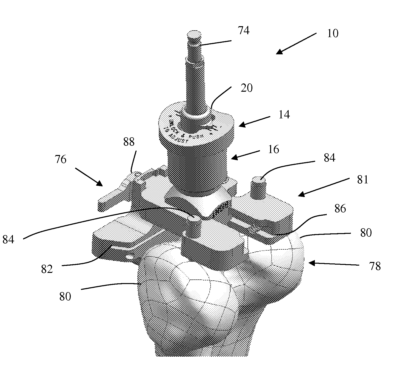
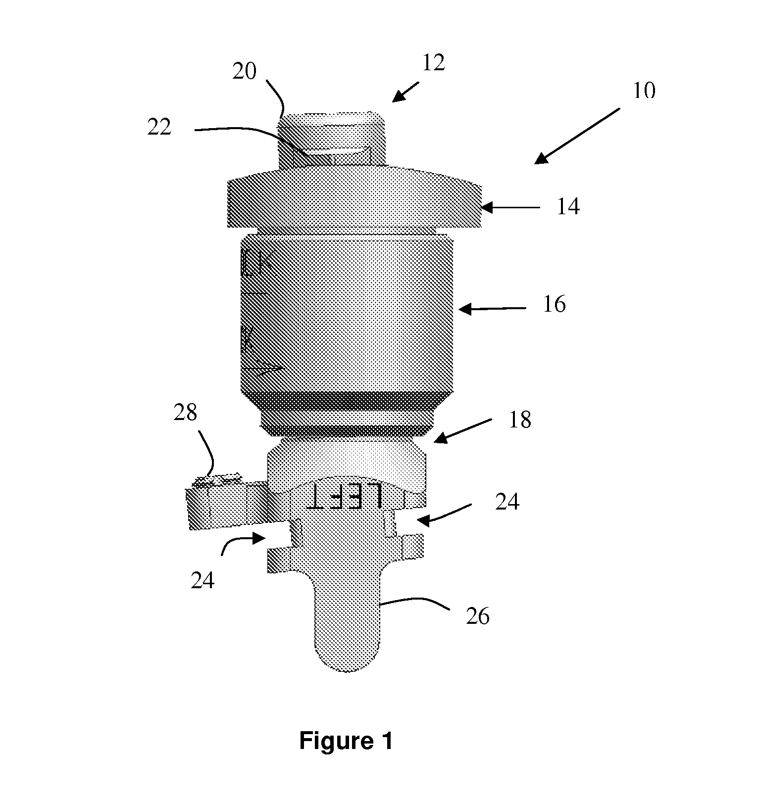
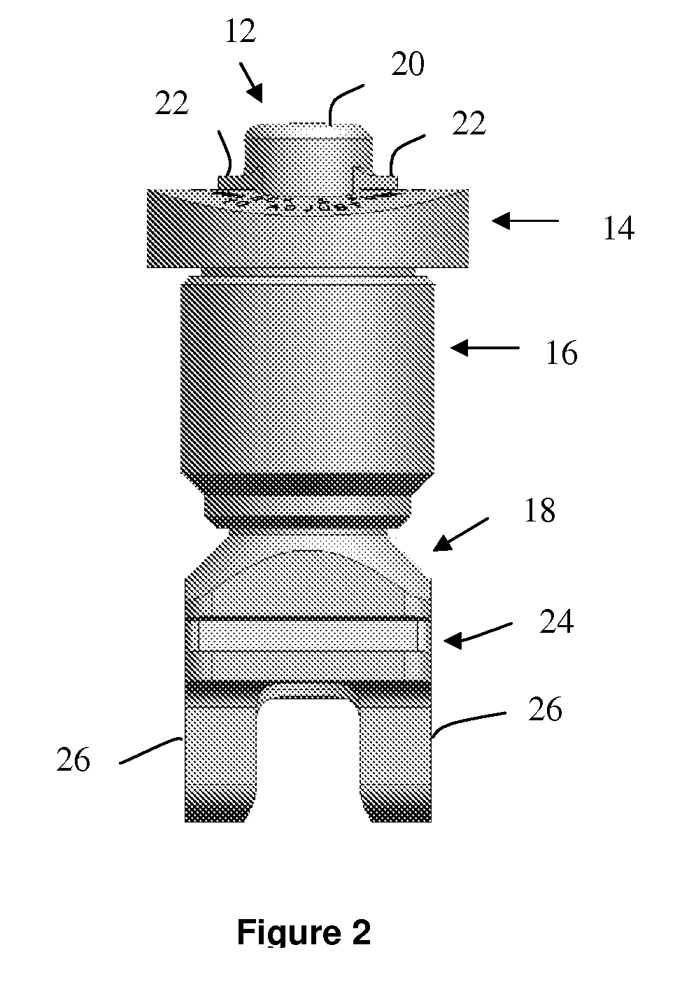
[0044]Referring to the accompanying drawings in which like reference numbers indicate like elements, FIG. 1 is an embodiment of a variable collet 10. The variable collet 10 includes an IM rod guide 12, an upper tensioner portion 14, a lower locking portion 16 and a distal cutting frame 18. The IM rod guide 12 includes a tensioner cap 20 and a varus / valgus indicator 22. The distal cutting guide frame 18 includes distal block assembly receiving slots 24, intracondylar guides 26 and a set screw 28. The collet 10 is configured to slide over an IM rod to position a distal cutting block in the proper orientation. The IM rod guide 12 orients the angle between the IM rod and the distal cutting block. The locking portion locks the angle in place. The distal cutting frame 18 sets the plane for the distal cutting guide.

[0045]The distal cutting block (examples of which are shown in FIGS. 9-12) is oriented in a plane defined by the receiving slots 24. The receiving slots are fixed with respect t...


PUM


Abstract

A device and method for resecting a distal portion of a femur comprises a distal cutting guide [98], a valgus guide [102], and a variable collet [10]. The distal cutting guide [98] is configured to overlie an anterior portion of the femur and comprises a slot for guiding a cutting tool across a distal portion of the femur. The valgus guide [102] is configured to connect to the distal cutting guide [98]. The valgus guide [102] is configured to align the slot of the distal cutting guide[98] at the proper varus/valgus angle. The variable collet [10] is configured to attach to an intramedullary rod and the valgus guide [102]. The variable collet [10] comprises a port [30] for receiving the intramedullary rod. The port [30] is angularly adjustable with respect to the valgus guide [102] such that adjusting the port [30] adjusts the varus/valgus angle of the distal cutting guide [98].

Description

CROSS-REFERENCE TO RELATED APPLICATIONS[0001]This application claims the benefit of U.S. Provisional Application No. 60 / 828,158, filed Oct. 4, 2006.BACKGROUND OF THE INVENTION[0002]1. Field of the Invention[0003]This invention relates generally to cutting guides and blocks for bone preparation of a femur and, more particularly, distal cutting guides for preparation of the distal portion of the femur.[0004]2. Related Art[0005]In preparing the knee for implantation of a prosthesis in knee replacement surgery (either total knee replacement or partial knee replacement), the distal femur requires cuts on the bone in precise locations and precise planar angles. In many instances, the first cut may be a distal cut on the femur. Further cuts, including anterior, posterior, and any intermediate angled cuts, may be referenced from the distal cut. Thus, the distal cut may be used to orient all other cuts on the distal portion of the knee. Properly aligning the distal cutting block prior to mak...

Claims


Application Information

Patent Timeline
Patent Type & Authority Applications(United States)
IPC IPC(8): A61B17/58
CPCA61B17/1764A61B17/155
Inventor DEES, ROGER RYANJORDAN, JASON SEAN
Owner SMITH & NEPHEW INC
Why Eureka
Try Eureka