Intramedullary nail

a technology of intramedullary nail and nail, which is applied in the field of intramedullary nail, can solve the problems of degree of adjustment, difficult operation, and inability to completely deny, and achieve the effects of easy insertion, correct adjustment, and simple construction

Inactive Publication Date: 2009-10-13
HOMS ENG INC
View PDF18 Cites 37 Cited by
  • Summary
  • Abstract
  • Description
  • Claims
  • Application Information

AI Technical Summary

Benefits of technology

[0010]Therefore, the present invention has been made to solve the above-described problems, and it is an object thereof to provide an engaging structure that can engage a bone fastener, which is inserted through a transverse hole provided in a nail body, easily and securely or accurately with respect to the nail body.
[0012]In particular, the adjusting means of the present invention is characterized in being provided so that a rotating operation is possible and having a cam engagement with the engaging member so as to change a controlling position for the engaging member according to its rotation angle in a condition substantially fixed in an axis direction.
[0013]According to the first aspect of the invention, since the adjusting member is, when being operated to rotate, changed in the controlling position for the engaging member in a condition substantially fixed in the axis direction, by appropriately setting the structure of a cam engagement, a desirable engaging condition for a bone fastener can be securely obtained without being affected by a subtle change in the operating amount, therefore such a necessity, as in the background art, of subtly adjusting the screwing amount in order to accurately set the position in the axis direction of adjusting screw is eliminated. In addition, since the operating amount for the adjusting member can also be reduced without lowering the operating accuracy by the structure of the cam engagement, it becomes possible to improve operationality. Accordingly, it becomes possible to set an engaging condition of the engaging member for the bone fastener inserted through the transverse hole easily and securely or accurately.
[0015]According to the second aspect of the invention, by controlling the engaging member to engage and retain a bone fastener from one side by use of the adjusting member and also charging the same from the other side by use of the elastic member, the position of the engaging member can be correctly adjusted by the simple construction. In addition, since the engaging member can be prevented from being projected from the transverse hole by a charge of the elastic member, the bone fastener can be easily inserted into the transverse hole and engagement between the bone fastener and engaging member can also be prevented. Accordingly, an engaging condition of the engaging member for the bone fastener can be set easily and securely or accurately.

Problems solved by technology

On the other hand, when the above-described intramedullary nail is used in a case where a fracture line exists between the femoral bone head portion and tubular portion, there is a danger that at the end of the femur, the bone head portion may be rotated around the axis line of the bone fastener inserted in the bone head portion.
However, in the aforementioned intramedullary nail, although it is necessary to screw the adjusting screw into the axial hole of the nail body and engage its distal end with the bone fastener after inserting the bone fastener through the transverse hole of the nail body and screwing the same toward the inside of the femur, since the engaged condition with the bone fastener is adjusted by a screwing amount of the adjusting screw, the degree of adjustment is difficult, therein a problem has existed.
For example, on a surgical site, normally, subtle operations such as returning the adjusting screw by a predetermined amount from a position where the adjusting screw has been completely screwed so that the bone fastener reaches the slide-lock condition have been performed, and it is impossible to completely deny a risk of the fastener reaching the slide-lock condition or the fastener reaching a perfectly free condition (being rotatable around the axis line thereof) to the contrary if this delicate operation is mishandled.
In addition, there is also a problem such that, since the adjusting screw has been merely screwed into the nail body, the adjusting screw is not sometimes correctly determined owing to a looseness of this screwed structure, this encourages failure of the operation, and operation resistance increases if the looseness of the screwed structure is reduced, therefore the operation becomes difficult.
Furthermore, in the case where a plurality of transverse holes are formed in a nail body and two or more bone fasteners are inserted (screwed) into a femoral bone head portion, there is a problem such that, bone fasteners inserted through transverse holes formed on the proximal end side of the nail body can be engaged and retained by the adjusting screw inserted through an opening provided at a proximal end portion of the nail body, whereas for bone fasteners inserted through the side of a distal end portion, the adjusting screw cannot be engaged therewith by being obstructed by the bone fasteners inserted through the proximal end portion side.

Method used


Image

  • Intramedullary nail
  • Intramedullary nail
  • Intramedullary nail

Examples


Embodiment Construction

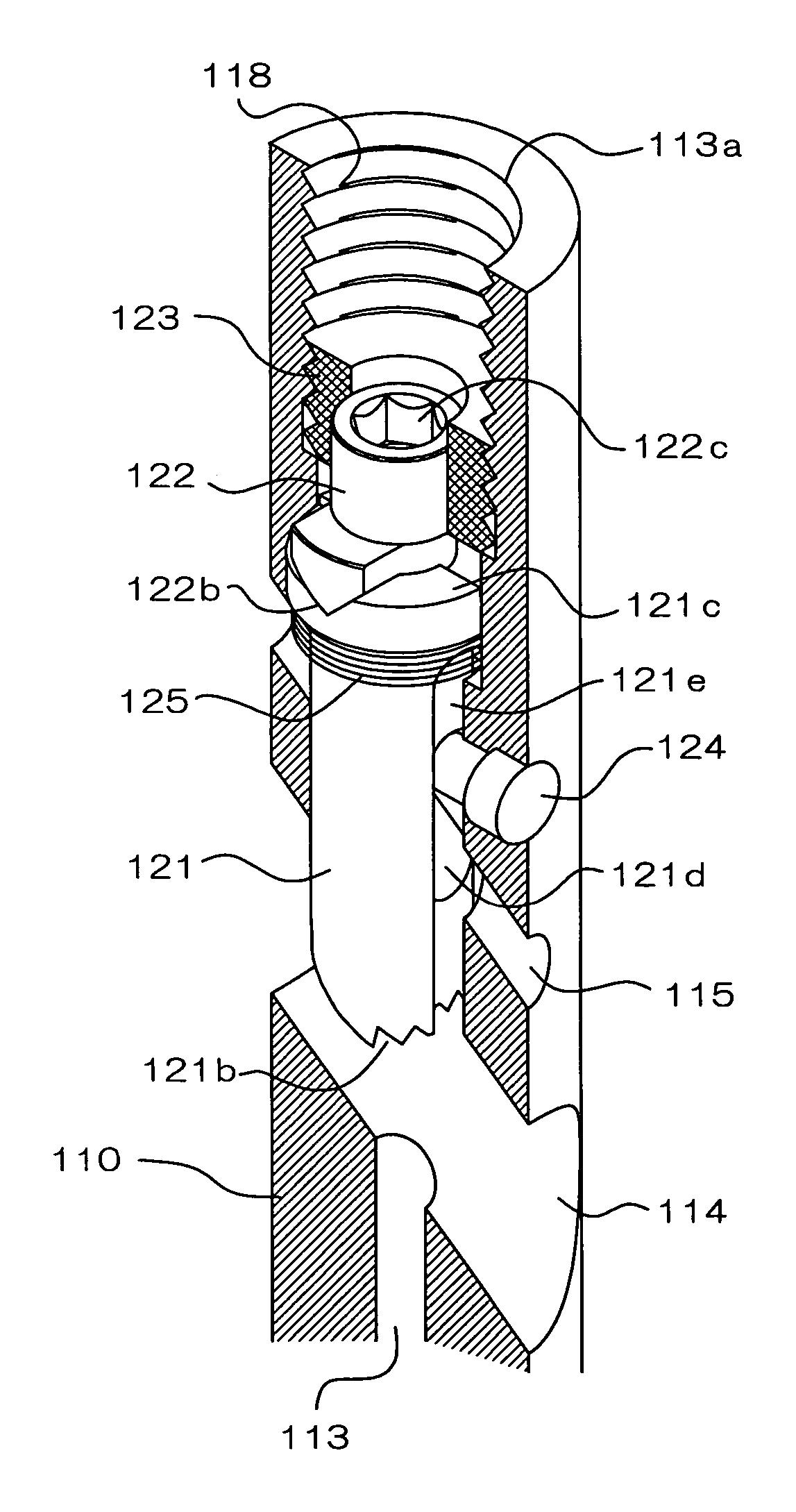
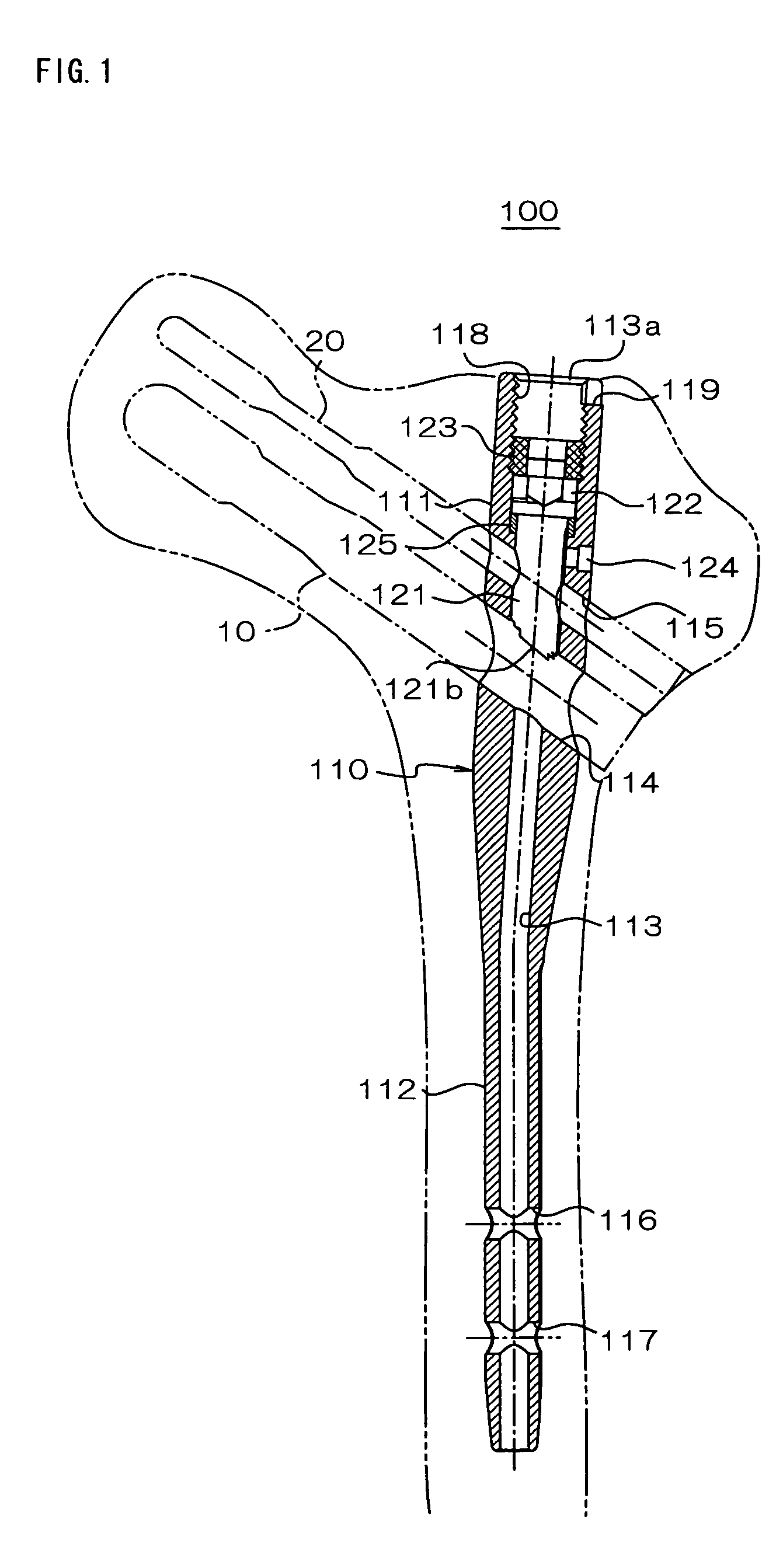
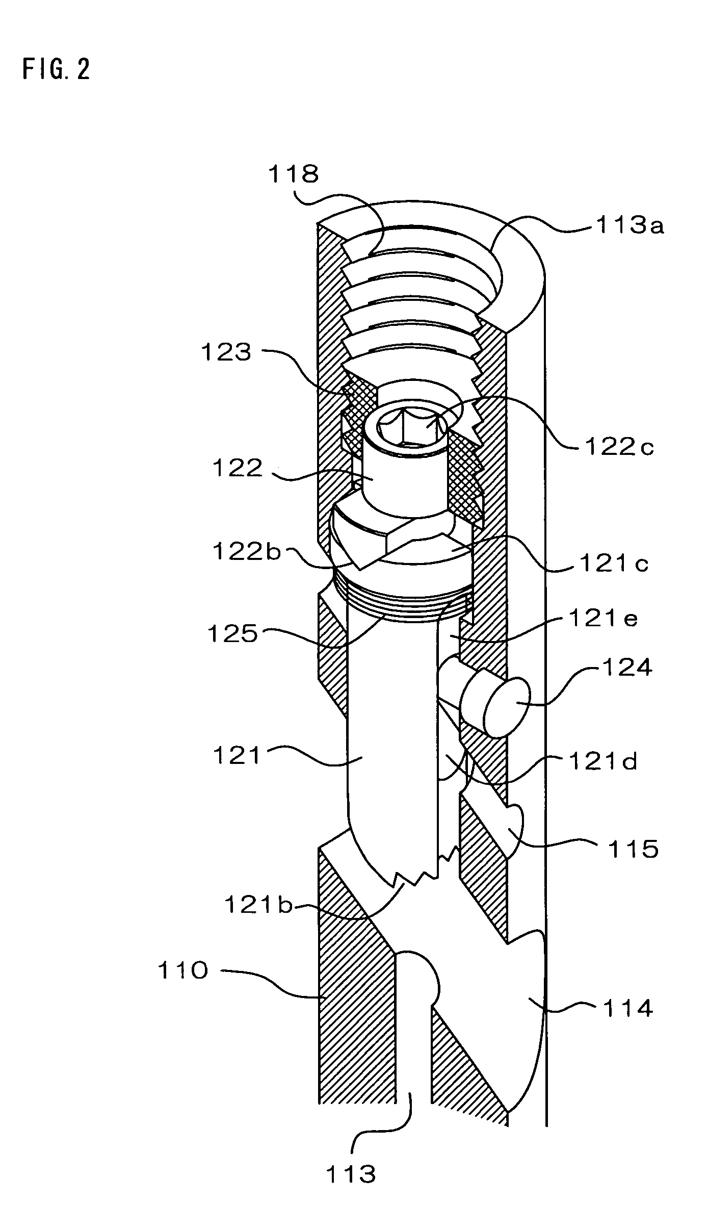
[0028]Hereinafter, an embodiment of the present invention will be described along with an illustrated example. FIG. 1 is a longitudinal sectional view showing an overall construction of an intramedullary nail 100 of the present embodiment, and FIG. 2 is an enlarged partial longitudinal section perspective view showing a longitudinal section of a proximal region of the intramedullary nail 100 in an enlarged manner. This intramedullary nail 100 has a nail body 110 extending axially from a proximal end portion to a distal end portion. This nail body 110 is preferably composed of a biocompatible material such as, for example, titanium, titanium alloy, a biodegradable resin and the like. The nail body 110 has a proximal region 111 provided at its proximal end side and a distal region 112 connected to the proximal region. The proximal region 111 preferably has a diameter larger than that of the distal region 112, and the proximal region 111 and the distal region 112 preferably have axis l...


PUM


Abstract

The present invention is an intramedullary nail (100) to be used by being intramedullarily inserted into a bone, having a nail body (110) comprising an axial hole (113) extending from an opening formed at a proximal end portion toward a distal end portion along an axis line and a transverse hole (114) intersecting with the axis line, and having: an engaging member (221) comprising an engaging portion (221b) at distal end thereof engageable with a bone fastener inserted through the transverse hole and arranged so as to be shiftable in the axial hole in a manner where the distal end portion is engageable and disengageable with the bone fastener (10); an adjusting member (222) controlling the position of the engaging member; and an elastic member (125) for charging, against the nail body, the engaging member in a direction opposite the controlling direction by the adjusting member.

Description

CROSS-REFERENCE TO RELATED PATENT APPLICATION[0001]This patent application claims priority on Japanese Patent Application No. 2003-429252 filed on Dec. 25, 2003. The entire disclosure of this Japanese Patent Application, including the specification, claims, drawings and summary, are also incorporated herein by reference.FIELD OF THE FIELD[0002]The present invention relates to an intramedullary nail, and in particular, it relates to a structure of an intramedullary nail preferred for a fracture treatment of an upper portion of a femur.BACKGROUND OF THE INVENTION[0003]Generally, as osteosynthesis means for treating fractures of upper portions of femurs, intramedullary nails comprising a nail body to be intramedullarily inserted from proximal parts of femurs have been used. These intramedullary nails include, for example, one as described in the specification of European Patent Publication NO. 0257118. This has an axial hole extending from an opening provided at a proximal end portion ...

Claims


Application Information

Patent Timeline
Patent Type & Authority Patents(United States)
IPC IPC(8): A61B17/56A61B17/58A61F2/30A61B17/78
CPCA61B17/744
Inventor SHINJO, AKIRAHAYANO, KIJYURO
Owner HOMS ENG INC
Why Eureka
Try Eureka