System for intramedullary rod fixation and method therefor

a technology of intramedullary rods and fixation methods, which is applied in the field of intramedullary rod systems for stabilizing bone segments, can solve the problems of reducing blood supply, affecting the healing time of the bone itself, and affecting the healing effect of the bone itsel

Active Publication Date: 2010-08-31
PEGA MEDICAL
View PDF16 Cites 38 Cited by
  • Summary
  • Abstract
  • Description
  • Claims
  • Application Information

AI Technical Summary

Benefits of technology

[0011]According to one aspect of the invention, a screw assembly for securing an intramedullary rod in a medullary canal of a bone is provided. The screw assembly includes a screw body with a shaft and at least one receiving bore that extends transversely through the shaft. The bore is adapted to receive an intramedullary rod. A securing member is movable toward the bore to thereby secure the rod to the screw assembly.

Problems solved by technology

Any longitudinal, transverse, or rotational movement of one fractured bone section relative to the other may cause a substantial delay in healing time or improper healing of the bone itself.
However, such an arrangement may cause injury to the surrounding outer layer and decrease blood supply and delay or inhibit bone healing.
Plates also tend to shield the bone from stress and decrease the strength of the underlying bone.
Although flexible nails have been utilized by some doctors (primarily in pediatric patients with small diameter long bones), there are drawbacks to their use.
For instance, the nails are not securely fixed within the intra medullary canal.
Moreover, flexible nails lack the rotational stability of rigid nails and normally cannot be used in highly unstable or comminuted fractures.
The distal end 34 may be left unanchored to allow for growth of the bone, resulting in unpredictable positioning of the rod.
Although this type of system may be acceptable for bones having relatively large cross sections, it is difficult to implement in smaller bone structures due to size restraints.
However, forming a hole in the 2-4 mm nail would be quite difficult, and the provision of a substantially smaller screw to fit in the hole would not provide sufficient cross-pinning to isolate movement of the nail or to fix it in a desired position.

Method used


Image

  • System for intramedullary rod fixation and method therefor
  • System for intramedullary rod fixation and method therefor
  • System for intramedullary rod fixation and method therefor

Examples


Embodiment Construction

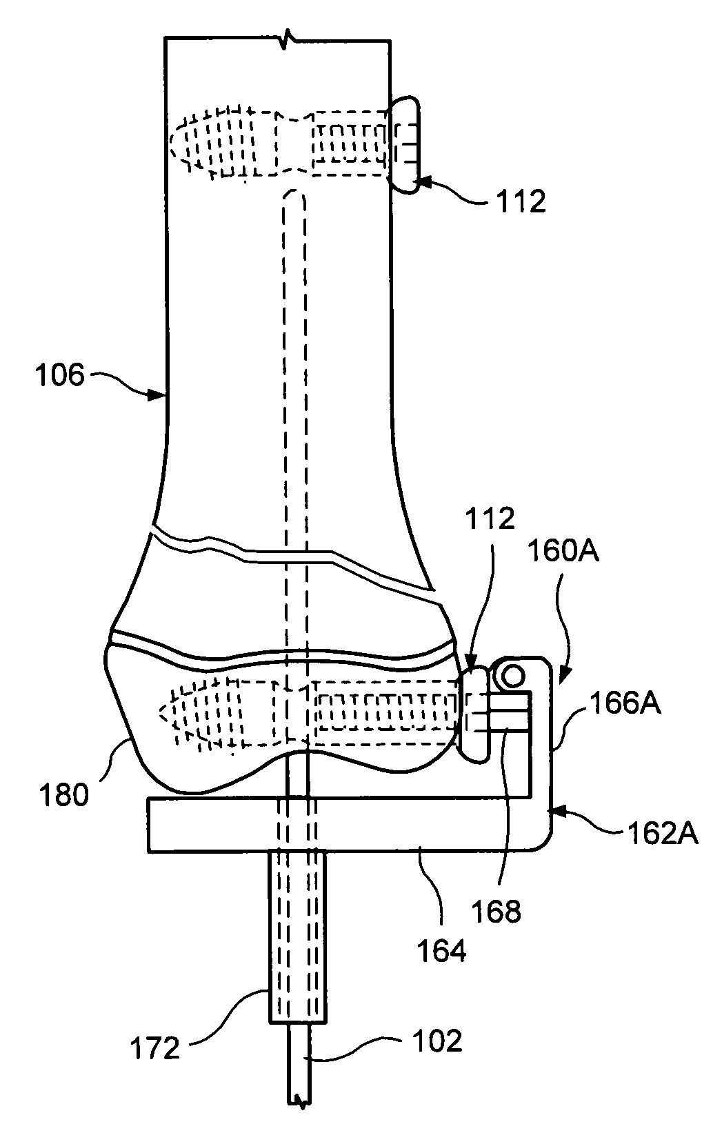
[0031]Referring to the drawings, and to FIG. 5 in particular, an intramedullary nailing system 100 in accordance with an exemplary embodiment of the present invention for affixing and / or mobilizing two or more separated bone segments, such as segments 114, 116, and 118, of a bone structure 106 is illustrated. The system 100 preferably includes an intramedullary nail or rod 102 (shown in hidden line) that is adapted to extend into the medullary canal 104 (also shown in hidden line) of the bone structure 106 with one or more fractures 108, 110 and a screw assembly 112 that anchors the rod 102 within the medullary canal to secure the bone segments together during the treatment process.

[0032]The system 100 of the present invention is especially suitable in pediatric orthopedics for fixation of fractured bones such as the tibia, femur and humerus, complications caused by osteogenesis imperfecta, pseudoarthrosis of the tibia, and so on. However, it will be understood that the present inve...


PUM


Abstract

A system and method for securing an intramedullary rod in a medullary canal of a long bone is provided. The system includes an intramedullary rod and a screw assembly for receiving the rod. The screw assembly has a transverse receiving bore for receiving the intramedullary rod and a securing member movable toward the bore for securing the rod to the screw assembly. An alignment jig may also be provided for aligning the rod with the receiving bore during installation.

Description

BACKGROUND OF THE INVENTION[0001]1. Field of the Invention[0002]The present invention relates generally to the treatment of bone fractures or abnormal bone conditions which require osteotomies, and more particularly to an intramedullary rod system for stabilizing bone segments.[0003]2. Description of Prior Art[0004]The fracture of certain bones, such as the femur, tibia, ulna, radius and humerous, requires substantial immobilization of the fractured bone sections in an abutting relationship during the healing process. Any longitudinal, transverse, or rotational movement of one fractured bone section relative to the other may cause a substantial delay in healing time or improper healing of the bone itself. In general, prior art provides various internal fixation approaches that have been used to immobilize the area surrounding the fracture site.[0005]One approach involves driving metallic pins through the two sections of bone to be joined and connecting them to one or more plates bea...

Claims


Application Information

Patent Timeline
Patent Type & Authority Patents(United States)
IPC IPC(8): A61B17/56
CPCA61B17/1717A61B17/72A61B17/725A61B17/8605A61B17/7291A61B17/8625A61B17/8685
Inventor GREEN, DANIEL W.MOLINO, JOSEPH L.
Owner PEGA MEDICAL
Why Eureka
Try Eureka