Method and system for securing an intramedullary nail

a technology for intramedullary nail and locking member, which is applied in the field of system and method for targeting and placement of locking member, can solve the problems of adding difficulty, difficult to use and rely on conventional targeting guides, and the most difficult procedural aspects of implanting an imn, etc., and achieves simple and efficient procedure, simple design, and the effect of solving the needs of distal targeting

Inactive Publication Date: 2010-06-01
BENTON BLAKE
View PDF37 Cites 44 Cited by
  • Summary
  • Abstract
  • Description
  • Claims
  • Application Information

AI Technical Summary

Benefits of technology

[0011]The present invention solves the distal targeting needs that are so prevalent in the market today. Also, the present invention includes guided proximal targeting mechanisms of relatively simple design that can be used with most contemporary intramedullary nails (IMN's). In this way, virtually any IMN locking position can be located in order to properly secure the implanted IMN. Also, the invention provides a simple and efficient procedure for securing the IMN.

Problems solved by technology

In contrast, one of the most difficult procedural aspects of implanting an IMN has been the location, alignment, drilling and subsequent placement of the distal locking screws.
This difficulty stems in part from distal deformations that occur in some IMN's when they are implanted in the affected medullary canal.
Such IMN distal end deformations make it difficult to use and rely on conventional targeting guides.
Also, tight manufacturing tolerances that are needed between the IMN and the interlocking screws adding to the difficulty.
Unfortunately, to ensure the drill hole is actually made in the desired location, such a system must still rely on the steady hand of the orthopedic surgeon, intense eye-hand coordination and is subject to the inaccuracies related to drill walk.
Unfortunately, contemporary apparatus fail to solve the problem of effectively targeting the distal locking hole positions.
The combination of the deformation of the implanted IMN, the slight shake that is natural in hand-held instruments, the drift that often occurs with contemporary drills when drilling through bone, and other factors make it difficult to actually drill a hole that properly aligns with a distal locking hole position.
Also, contemporary devices do not provide a reliable overall system for targeting and securing both proximal and distal locking hole positions.

Method used


Image

  • Method and system for securing an intramedullary nail
  • Method and system for securing an intramedullary nail
  • Method and system for securing an intramedullary nail

Examples


Embodiment Construction

[0049]The drawings show a device embodying the principles and concepts of the present invention. It should be noted that although the figures are directed to the preferred embodiment, other applications of the instant invention are anticipated, as discussed more fully below.

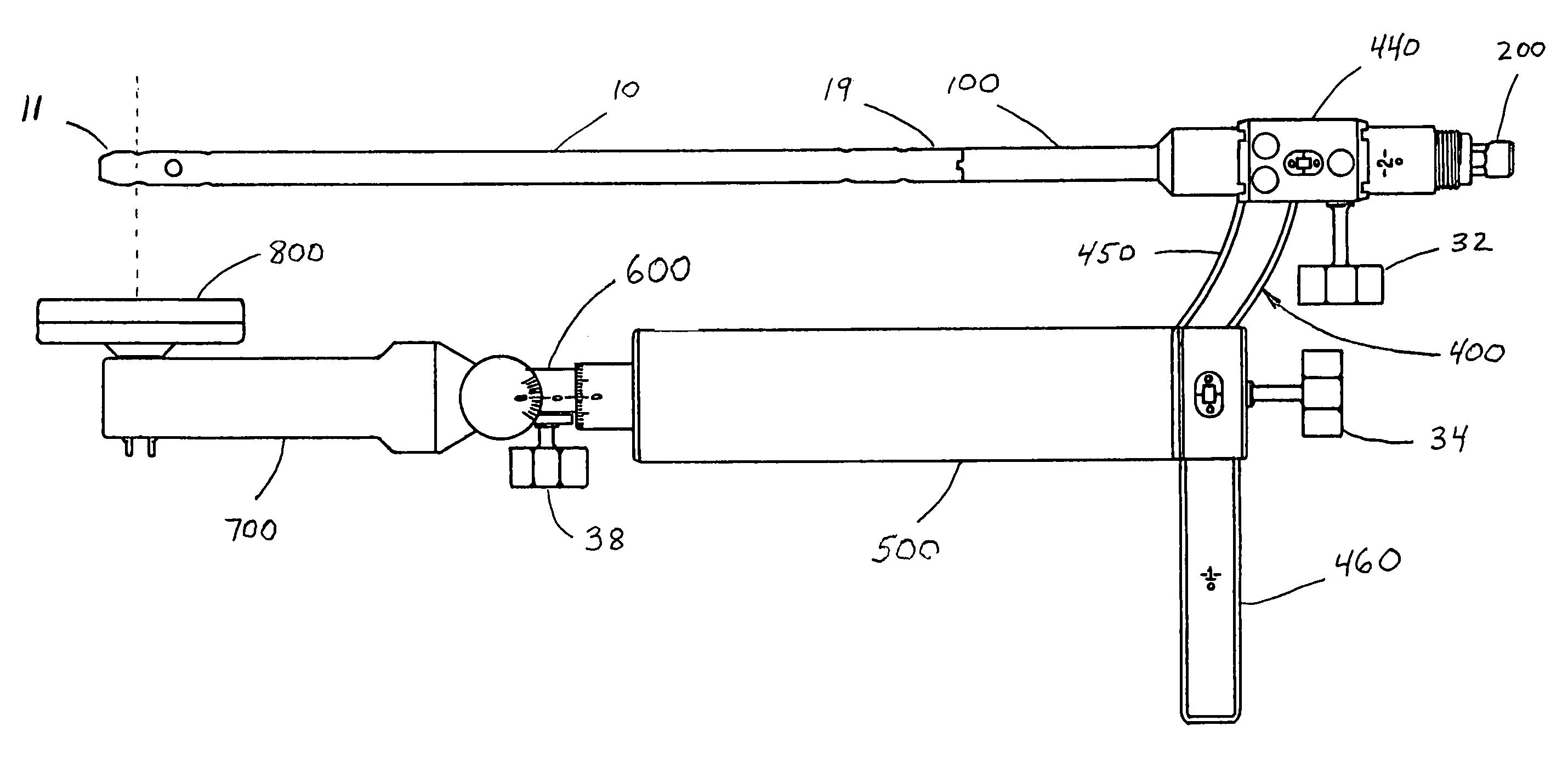
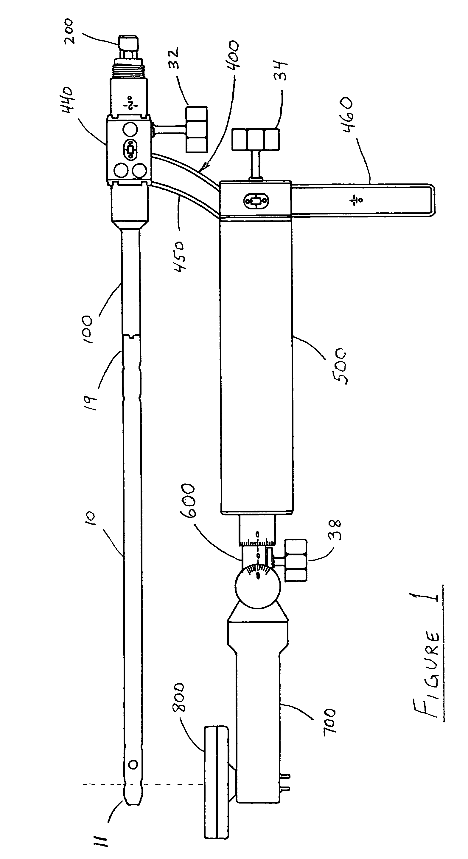
[0050]FIG. 1 shows major portions of a modular assembly for an intramedullary nail (IMN) securing system. An IMN 10 is shown having a distal end 11 depicted on the left side and an opposing proximal end 19. In one assembled embodiment, a nail adapter 100 is preferably coupled to the proximal end 19 of the IMN 10 by a coupler rod 200 that fits inside and extends the length of the nail adapter 100. In the assembled state, the coupler rod 200 is preferably threaded and engaged at one end with the IMN 10, while holding the coupler rod 200 in place with flange elements 210 at an opposite end. A bridge adapter 400 preferably has a cylindrical mounting collar 440 at one end that fits onto the nail adapter 100. A central...


PUM


Abstract

A device, method and system adapted to determine a targeting position on a surgically implantable nail adapted to be used in internal fixation of a bone, the nail comprising a distal end and a proximal end, the device including an extension rod comprising a longitudinal axis and adapted to be detachably coupled to the proximal end of the nail, a bridge member adjustably secured to the extension rod and extending radially from the longitudinal axis of the extension rod, a position of the bridge member on the extension rod being rotationally and longitudinally adjustable with respect to the longitudinal axis of the extension rod, and a targeting arm adjustably coupled to the bridge member and extending from the bridge member toward the distal end of the locking nail, the targeting arm comprising a drill guide.

Description

BACKGROUND OF THE INVENTION[0001]1. Field of the Invention[0002]The present invention relates to the implantation of an intramedullary nail (IMN) for repair of long bone internal fractures. More specifically, the present invention relates to a system and method for targeting and placement of locking members in an IMN by means of magnetic and mechanical guidance. The present invention provides guidance for both proximal and distal targeting in an IMN.[0003]2. Brief Description of the Related Art[0004]In order to repair long bone fractures it is often necessary to use implants known as intramedullary nails (IMN). For example, an IMN can be used to repair an internal fracture of the femoral or tibial shafts. Advantages associated with the usage of an IMN include providing sufficient stability to maintain alignment and length, and limit rotation of the fracture site. Further advantages include minimally invasive techniques, reduced hospitalization, earlier postoperative ambulation, and ...

Claims


Application Information

Patent Timeline
Patent Type & Authority Patents(United States)
IPC IPC(8): A61B17/58A61B17/60A61F2/00
CPCA61B17/1707A61B17/1725A61B17/72
Inventor BENTON, BLAKE
Owner BENTON BLAKE
Why Eureka
Try Eureka