Shielded wire

A technology of shielding wire and shielding layer, applied in the direction of braided wire conductors, conductors, electrical components, etc.

Inactive Publication Date: 2010-08-18
YAZAKI CORP
View PDF2 Cites 8 Cited by
  • Summary
  • Abstract
  • Description
  • Claims
  • Application Information

AI Technical Summary

Problems solved by technology

However, the portion where the defect is generated has not be

Method used


Image

  • Shielded wire
  • Shielded wire
  • Shielded wire

Examples


Embodiment Construction

[0032] Embodiments of the present invention will be described below with reference to the accompanying drawings.

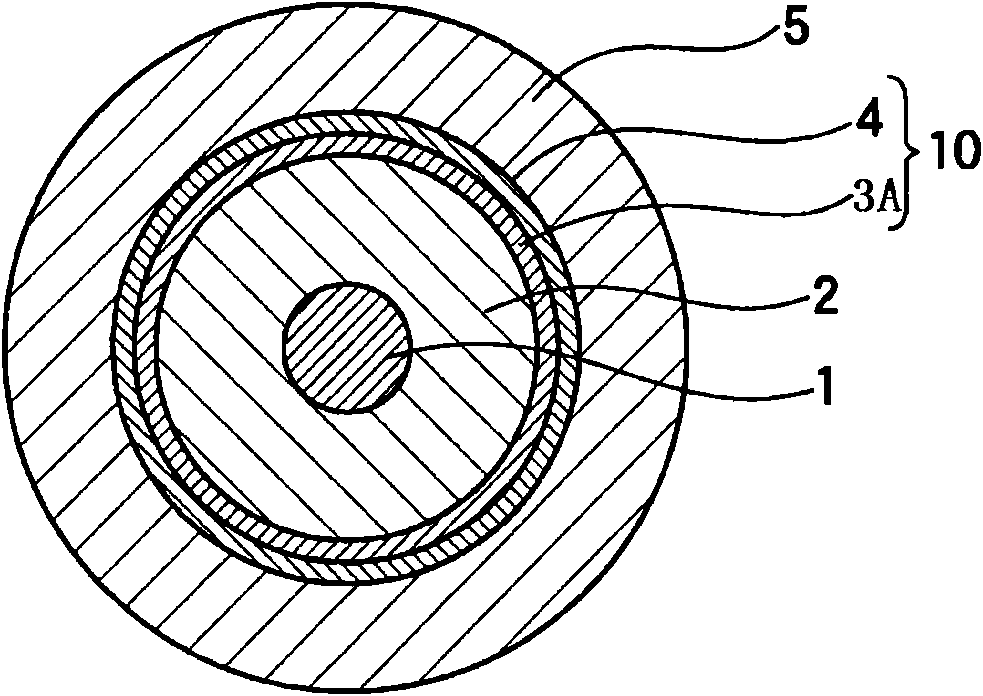
[0033] figure 1 is a sectional view of the single-core shielded wire according to the first embodiment of the present invention.

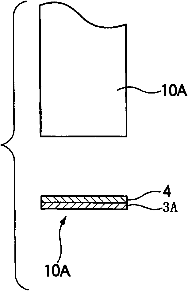
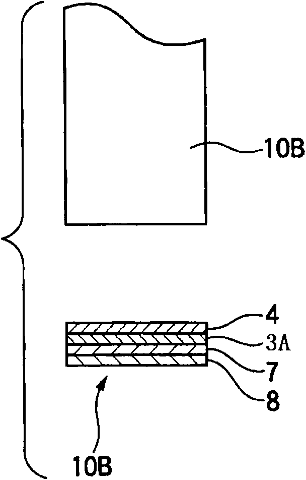
[0034] The shielded wire has an inner conductor 1 , an insulating layer 2 (dielectric layer) covering the outer side of the inner conductor 1 , a shielding layer 10 surrounding the outer side of the insulating layer 2 , and a protective layer 5 covering the outer side of the shielding layer 10 . The shielding layer is characterized in that the shielding layer 10 is constructed as a double-layer structure having a first electromagnetic shielding layer 3A and a second electromagnetic shielding layer 4; the first electromagnetic shielding layer 3A has a metal foil such as aluminum, copper, etc., and the second electromagnetic shielding layer The electromagnetic shielding layer 4 has a conductive resin provided on the outer side of the f...


PUM


Abstract

A shielded wire includes an internal conductor, an insulating layer covering the internal conductor, a shielding layer covering the insulating layer, and a protective layer covering the shielding layer. The shielding layer includes a first electromagnetic shielding layer and a second electromagnetic shielding layer which is directly provided on an outside of the first electromagnetic shielding layer. The first electromagnetic shielding layer has at least one of a metal braid and a metal foil, and the second electromagnetic shielding layer has a conductive resin.

Description

technical field [0001] The present invention relates to a shielded wire which is mainly suitable for wiring from a stationary part to a movable part of a vehicle. Background technique [0002] For example, if Figure 4 As shown, a shielded wire such as a single-core shielded wire includes an inner conductor 101, an outer insulating layer 102 (dielectric layer) covering the inner conductor 101, an outer shielding layer 103 wound around the insulating layer 102, and an outer shielding layer 103 covering the shielding layer 103. The outer protective layer 105 (housing). [0003] Common types of shielded wires are braided shielded wires in which the shield has a metal braid, foil shielded wires in which the shield has metal foil (for example, aluminum foil, copper foil, etc.), and braided and foil shielded wires. Both foil / braid shielded wires. [0004] The braided shielded wire has a structure in which an insulating layer (electrolyte) covers an inner conductor, a metal braid...

Claims


Application Information

Patent Timeline
IPC IPC(8): H01B7/04H01B5/14H01B5/12H01B5/16
CPCH01B7/04
Inventor 八木大亮
Owner YAZAKI CORP
Why Eureka
Try Eureka