

Integrated coupling type intelligent monitoring bearing
Patent Information
- Authority / Receiving Office
- CN · China
- Patent Type
- Patents(China)
- Current Assignee / Owner
- CHONGQING UNIV
- Publication Date
- 2011-08-31
Smart Images
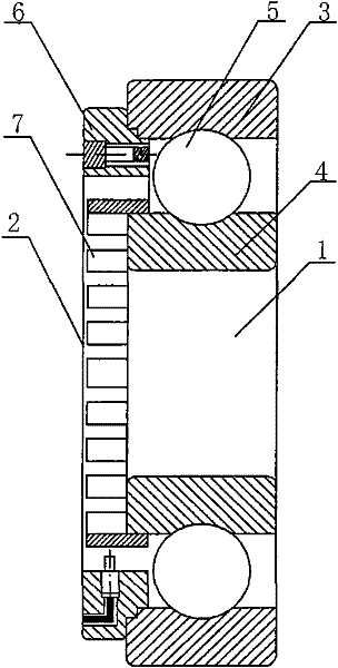
Figure 1 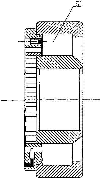
Figure 2 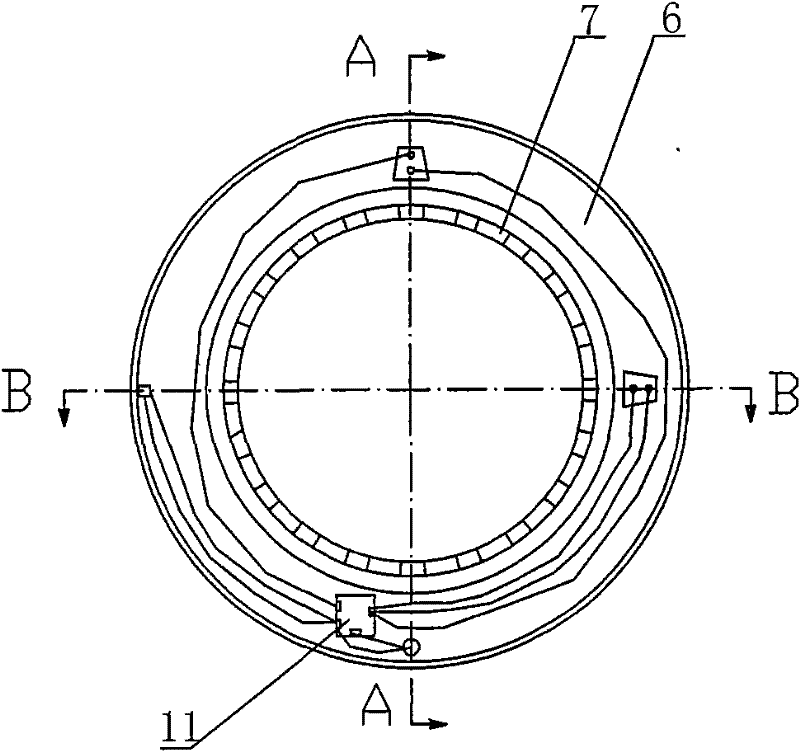
Figure 3
Abstract
Description
technical field
[0001] The invention belongs to bearings, in particular to a novel integrated coupling intelligent monitoring bearing applied to bearing state detection. Background technique
[0002] The current integrated smart bearings have two structural forms: external and embedded. The external combination method does not destroy the structure of the bearing but changes the overall size of the traditional bearing. At the same time, the characteristics of this type of combination determine that there is a certain distance between the sensing component and the source of the fault, so that the acquired signal cannot truly reflect the bearing. This method cannot be used for early detection of bearing fault characteristics, because the bearing fault detection with this structure cannot guarantee the reliability of the signal; the embedded combination method is very close to the source of the measured signal, and the signal The intermediate interface of transmission is reduc...