Installing method for refrigerator and its temperature sensor

A technology of temperature sensor and installation method, which is applied in household refrigerators, household refrigeration devices, evaporators/condensers, etc., and can solve problems such as unstable installation, large changes in perceived temperature, and inability to quickly control the on/off of compressor 8 , to achieve the effect of easy transportation or storage, and shorten the opening/closing time

Inactive Publication Date: 2004-09-22
LG ELECTRONICS INC
View PDF0 Cites 1 Cited by
  • Summary
  • Abstract
  • Description
  • Claims
  • Application Information

AI Technical Summary

Problems solved by technology

[0010] However, in the above-mentioned direct-cooling refrigerator of the prior art, the electrothermal component 16 of the aforementioned temperature sensor is in line contact with the inner casing 4, so it takes a certain amount of time for the heat of the aforementioned inner casing 4 to be transferred to the electrothermal component 16 of the temperature sensor. The on / off of the compressor 8 cannot be quickly controlled according to the temperature change of the storage room F. In addition, because a part of the electric heating component 16 of the aforementioned temperature sensor is easily in poor contact with the aforementioned internal housing 4, there is a deterioration in the temperature sensing performance, and the sensing temperature big change
[0011] And, in the direct cooling type refrigerator of above-mentioned prior art, the electrothermal component 16 of aforementioned temperature sensor is fixed on the aluminum strip 19, and aforementioned aluminum strip 19 is fixed on inner housing 4, so the electrothermal component 16 of aforementioned temperature sensor is installed Strong, external collisions, etc. are likely to cause poor contact between the electric heating component 16 of the temperature sensor and the inner casing 4

Method used


Image

  • Installing method for refrigerator and its temperature sensor
  • Installing method for refrigerator and its temperature sensor
  • Installing method for refrigerator and its temperature sensor

Examples


Embodiment Construction

[0034] Embodiments of the present invention will be described in detail below with reference to the drawings.

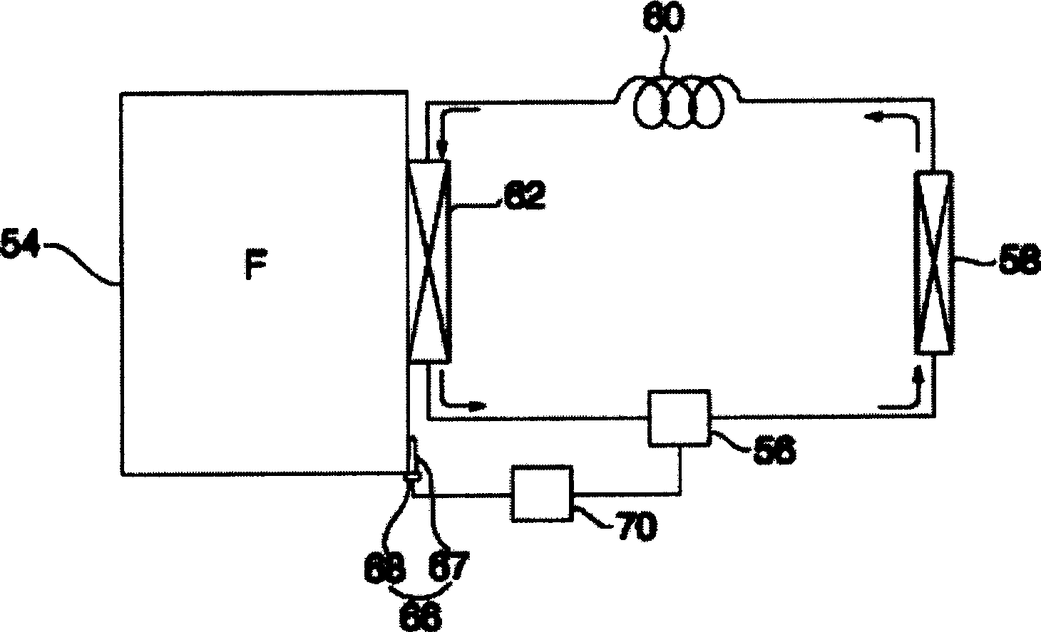
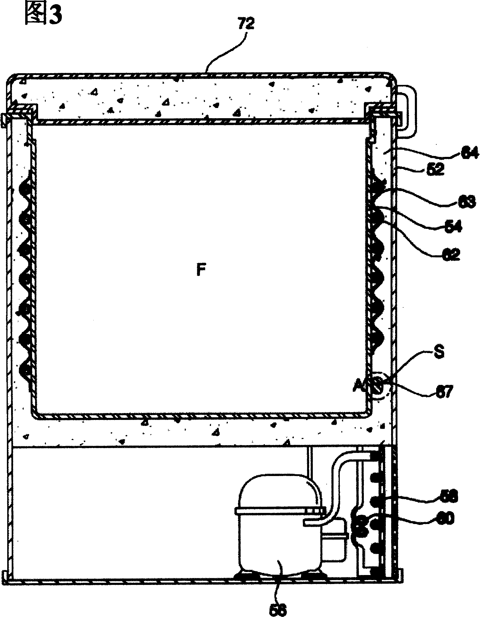
[0035] figure 2 It is a block diagram showing the cycle of the first embodiment of the direct cooling refrigerator of the present invention, and Fig. 3 is an internal structure diagram showing the first embodiment of the direct cooling refrigerator of the present invention, Figure 4 It is an enlarged view of part A shown in FIG. 3 .

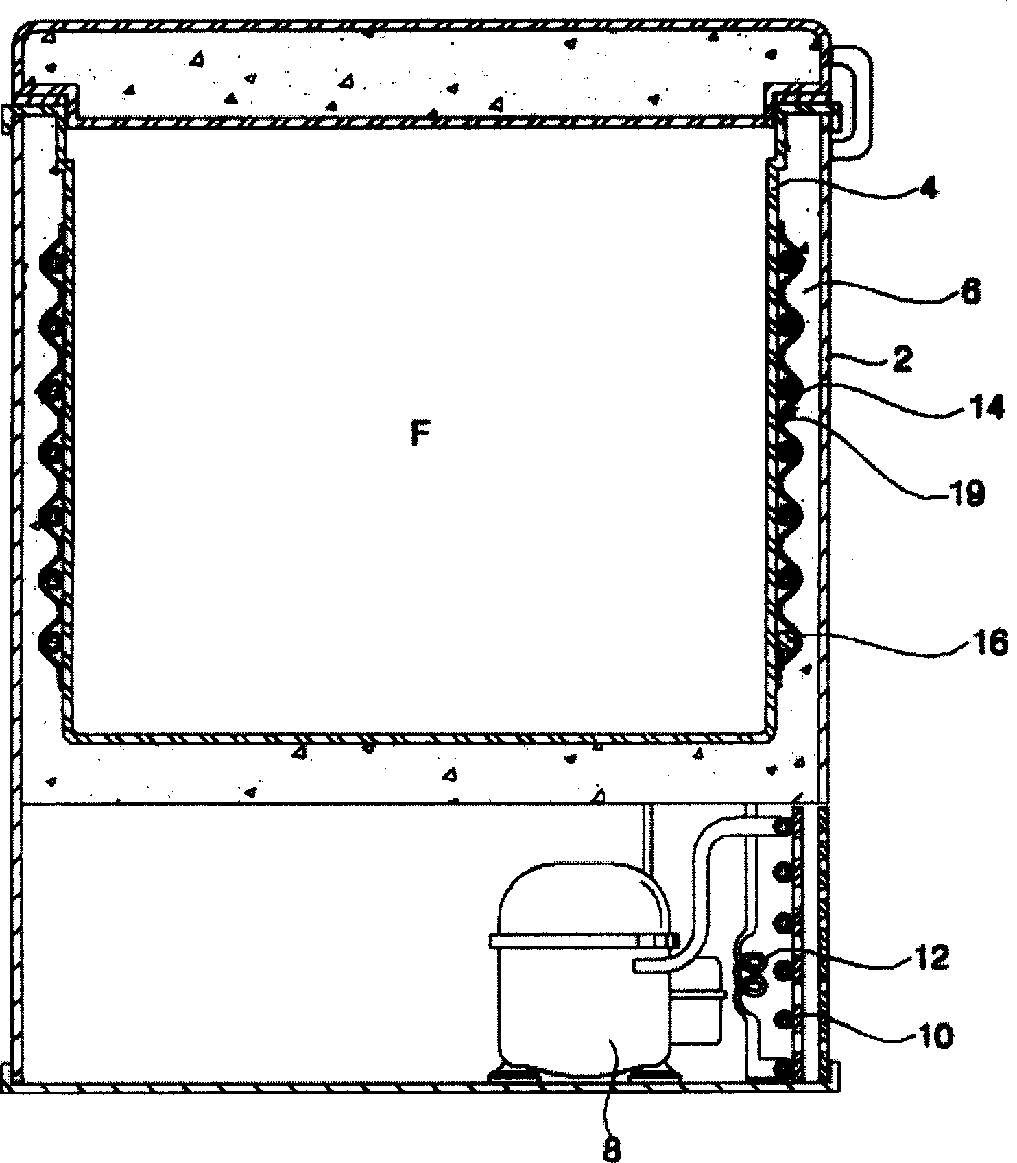
[0036] Such as Figure 2 to Figure 4 As shown, the direct cooling refrigerator of the present embodiment includes an outer casing 52 forming the outer shape of the refrigerator; an inner casing 54 forming a storage chamber F arranged in the aforementioned outer casing 52; a compressor for compressing refrigerant 56; a condenser 58 for condensing the high-pressure refrigerant gas passing through the compressor 56 into a liquid state; an expansion mechanism 60 for decompressing the refrigerant passing through the condenser 58; the ref...


PUM


Abstract

A direct cooling type refrigerator controlling the temperature thereof, reducing the ON / OFF time of its compressor, thereby preventing the temperature deviation of its storage compartment from increasing over a predetermined value. The refrigerator includes an outer casing defining an appearance of the refrigerator, an inner casing arranged within the outer casing, and defined with a storage compartment, an insulator interposed between the outer casing and the inner casing, a compressor for compressing a refrigerant, an evaporator arranged to be in contact with the inner casing, and adapted to cool the inner casing in accordance with evaporation of a refrigerant passing therethrough, a temperature sensor provided with a surface contact area closely contacting the inner casing, and adapted to sense a temperature of the inner casing, and a control unit for controlling the compressor in accordance with the temperature sensed by the temperature sensor.

Description

technical field [0001] The invention relates to a direct-cooling refrigerator, in particular to a direct-cooling refrigerator in which the contact area between the inner housing forming the storage room and the temperature sensor is large, so that the temperature change of the storage room can be correctly and quickly sensed and the compressor can be controlled. How to install a refrigerator and its temperature sensor. Background technique [0002] In general, refrigerators are classified into two types according to their cooling methods. That is, a direct cooling type refrigerator that cools the storage room by directly cooling the inner case of a storage room forming a freezer or a refrigerating room using an evaporator, and a cooling fan that supplies cold air generated by heat exchange with the evaporator to the storage room Indirect refrigerator. [0003] Such as figure 1 As shown, a common direct-cooling refrigerator includes an outer casing 2 forming the outer shap...

Claims


Application Information

Patent Timeline
Patent Type & Authority Applications(China)
IPC IPC(8): F25D23/00F25D11/00F25D23/06F25D29/00
CPCF25D2400/10F25D2700/10F25D29/005F25B2339/023F25D23/061F25D29/00
Inventor 李泰喜金京植金亮圭金世荣全灿镐李允硕
Owner LG ELECTRONICS INC
Why Eureka
Try Eureka