Centrifugal fan
一种离心式风扇、叶片的技术,应用在加热方式、非变容式泵、空间供热和通风等方向,能够解决气流速度降低、叶片16性能降低等问题
- Summary
- Abstract
- Description
- Claims
- Application Information
AI Technical Summary
Problems solved by technology
Method used
Image

Examples
no. 1 Embodiment approach
[0069] Below, refer to Figure 1 to Figure 5 A first embodiment in which a centrifugal fan (turbo fan) of the present invention is applied to an indoor unit of a ceiling-embedded air conditioner will be described.
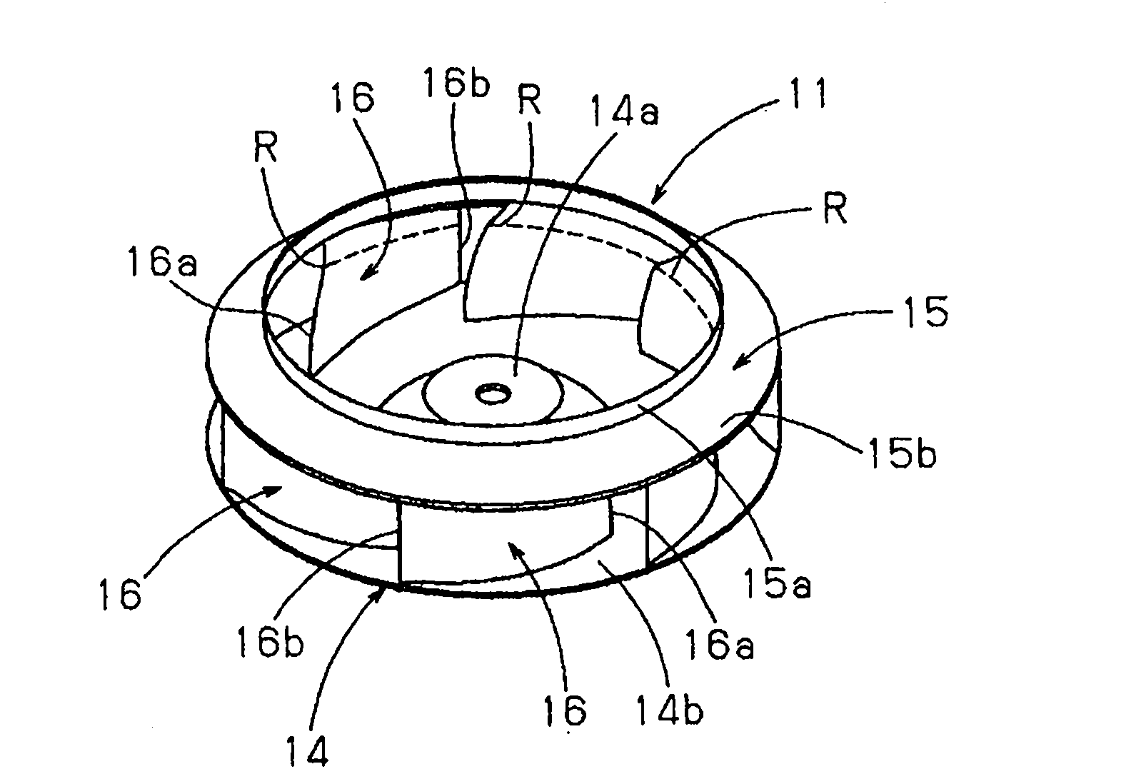
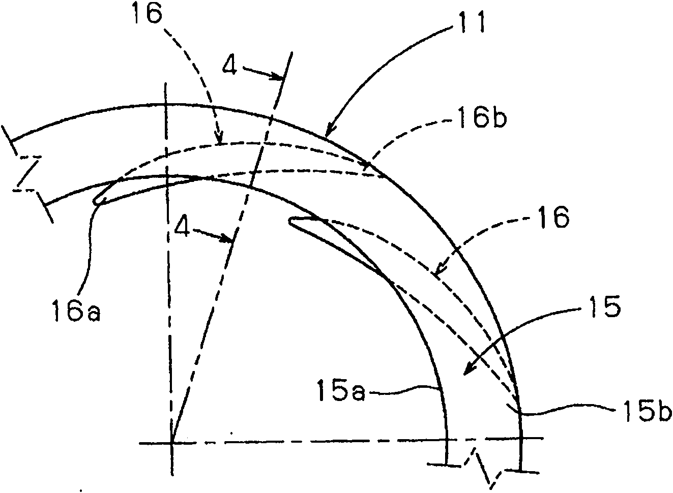
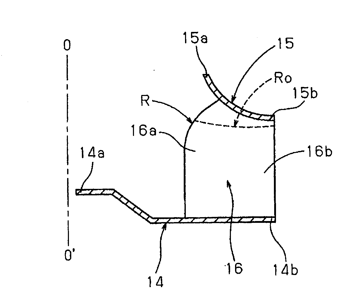
[0070] Such as Figure 1 ~ Figure 3 As shown, the centrifugal fan (turbo fan) 11 has a circular main board (hub) 14, a cylindrical side plate (shield) 15, and has a plurality of blades (moving blades) between the main board 14 and the side plate 15. )16. Main board 14 is fixed on Figure 31 The rotational drive shaft 13a of the fan motor 13 is shown. The blades 16 are arranged along the circumferential direction at a predetermined blade angle and at predetermined intervals. The side plate 15 has two open ends having different outer diameters. One open end of the side plate 15 forms an air suction port for guiding air in the centrifugal direction inside the impeller. The air outlet part 6c of the bell mouth 6 is loosely fitted in the air suction end part 15a o...
no. 2 Embodiment approach
[0080] Below, refer to Figure 6 ~ Figure 10 A second embodiment in which the centrifugal fan of the present invention is applied to an indoor unit of a ceiling-embedded air conditioner will be described.
[0081] In the second embodiment, if Figure 6 ~ Figure 10 As shown, in the first embodiment, the curved portion is also formed in the vicinity of the connecting portion between the blade 16 and the main plate 14 of the centrifugal fan. As a result, the horseshoe-shaped eddy flow generated on both surfaces of the blade 16 is suppressed at the connecting portion between the blade 16 and the main plate 14 .
[0082] Such as Figure 1 to Figure 5 As in the first embodiment shown, when the blades 16 are vertically provided with respect to the planar main plate 14, as Figure 36 ~ Figure 38 As shown, a horseshoe-shaped vortex is formed centering on the intersection of the main plate 14 and the leading edge 16 a of the blade 16 . Since the formation and increase of such a hors...
no. 3 Embodiment approach
[0088] Below, refer to Figure 12 A third embodiment in which the centrifugal fan of the present invention is applied to an indoor unit of a ceiling-embedded air conditioner will be described.
[0089] In the third embodiment, if Figure 12 As shown, it is characterized in that the same horseshoe-shaped eddy current suppressing portion as in the second embodiment is constituted by the forward vane structure S. The advancing wing configuration S is formed by protruding a portion of the leading edge 16 a of the blade 16 close to the main plate 14 by a predetermined size toward the center of the main plate 14 .
[0090] According to the structure, such as Figure 12 As shown by the phantom line arrows of , on both sides of the blade 16, a pressing force by the suction airflow (main flow) acts on the connecting portion between the leading edge 16a of the blade 16 and the main plate 14. Therefore, it is difficult to form a horseshoe-shaped eddy, or the horseshoe-shaped eddy can ...
PUM
 Abstract
Description
Claims
Application Information
 - R&D
- Intellectual Property
- Life Sciences
- Materials
- Tech Scout
- Unparalleled Data Quality
- Higher Quality Content
- 60% Fewer Hallucinations
Browse by: Latest US Patents, China's latest patents, Technical Efficacy Thesaurus, Application Domain, Technology Topic, Popular Technical Reports.
© 2025 PatSnap. All rights reserved.Legal|Privacy policy|Modern Slavery Act Transparency Statement|Sitemap|About US| Contact US: help@patsnap.com