Right/left independent action column type vulcanization machine

An independently operated and equipped technology, applied in the field of vulcanizers, which can solve problems such as large installation space

Active Publication Date: 2010-09-08
MITSUBISHI HEAVY IND MACHINERY SYST LTD
View PDF1 Cites 7 Cited by
  • Summary
  • Abstract
  • Description
  • Claims
  • Application Information

AI Technical Summary

Benefits of technology

The technical effect of this patented design allows for efficient placement of both devices within one column that makes it smaller overall without sacrificing performance compared with other designs like linear configurations.

Problems solved by technology

This patented technical problem addressed by this patents relates to reducing the size required when replacing different types of equipment due to their independent operation between them. Specifically, current cylindrical vapor inflators have limitations because they require a lot more space than smaller tires without being able to accommodate larger tires.

Method used


Image

  • Right/left independent action column type vulcanization machine
  • Right/left independent action column type vulcanization machine
  • Right/left independent action column type vulcanization machine

Examples


Embodiment

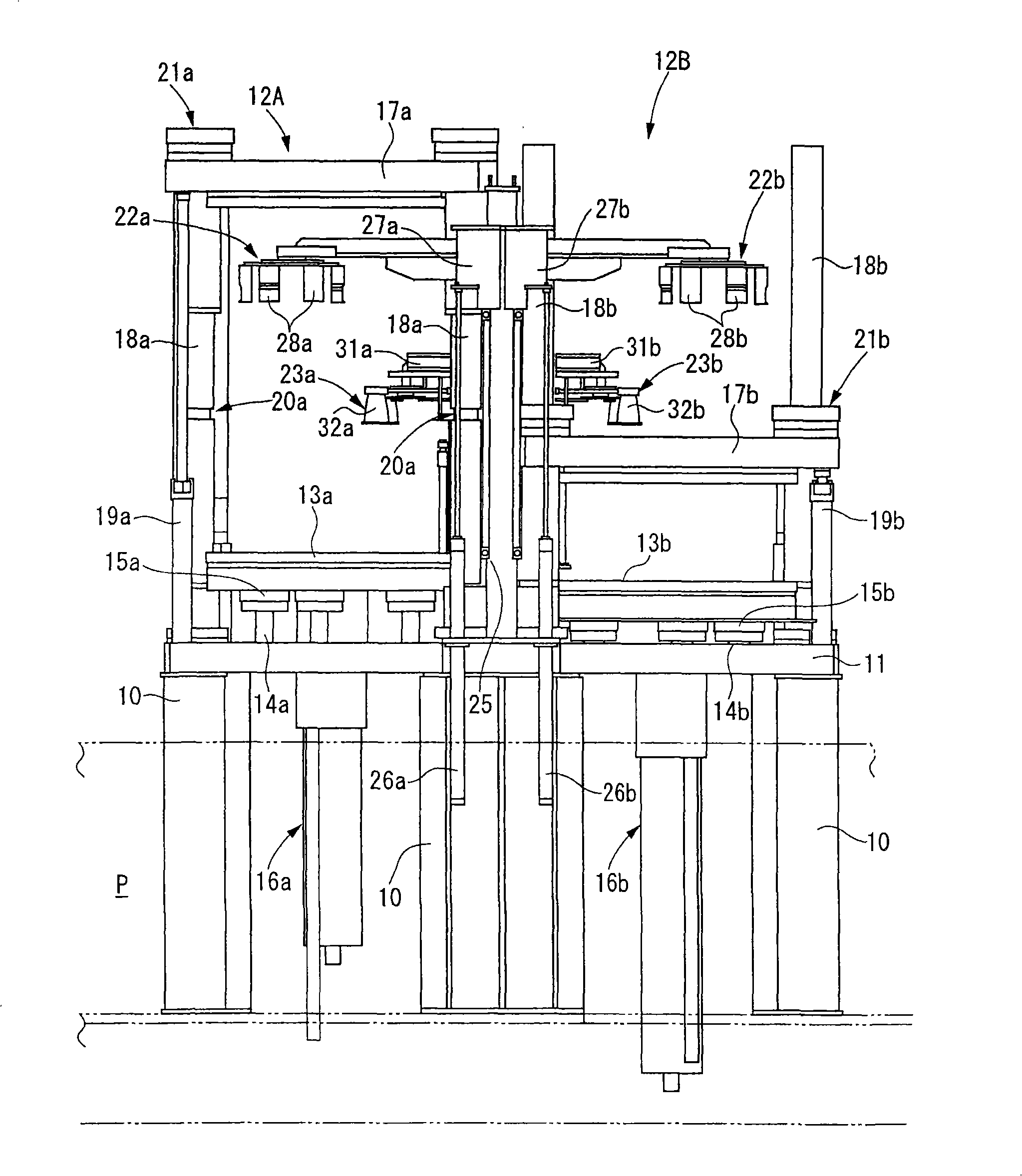
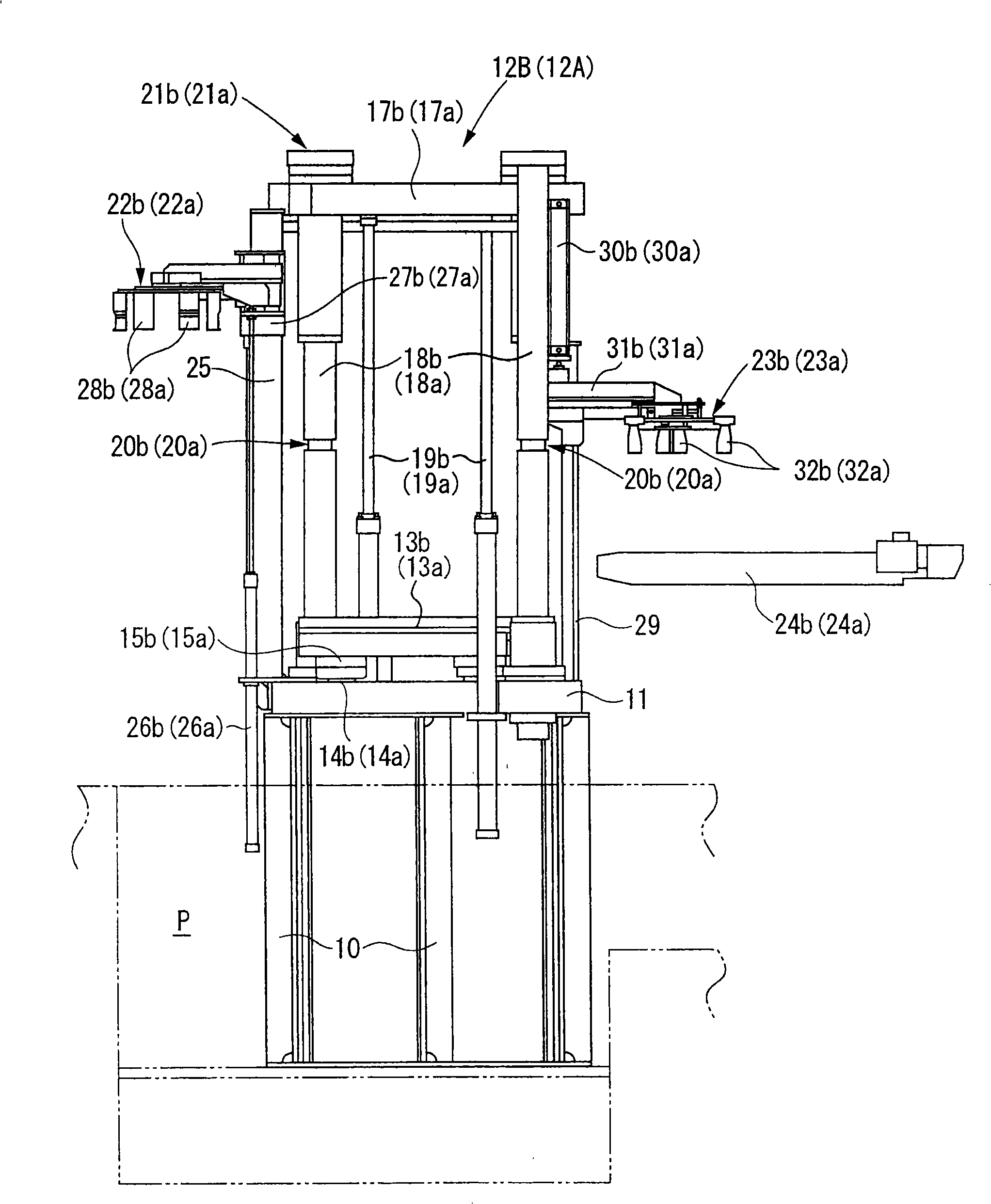
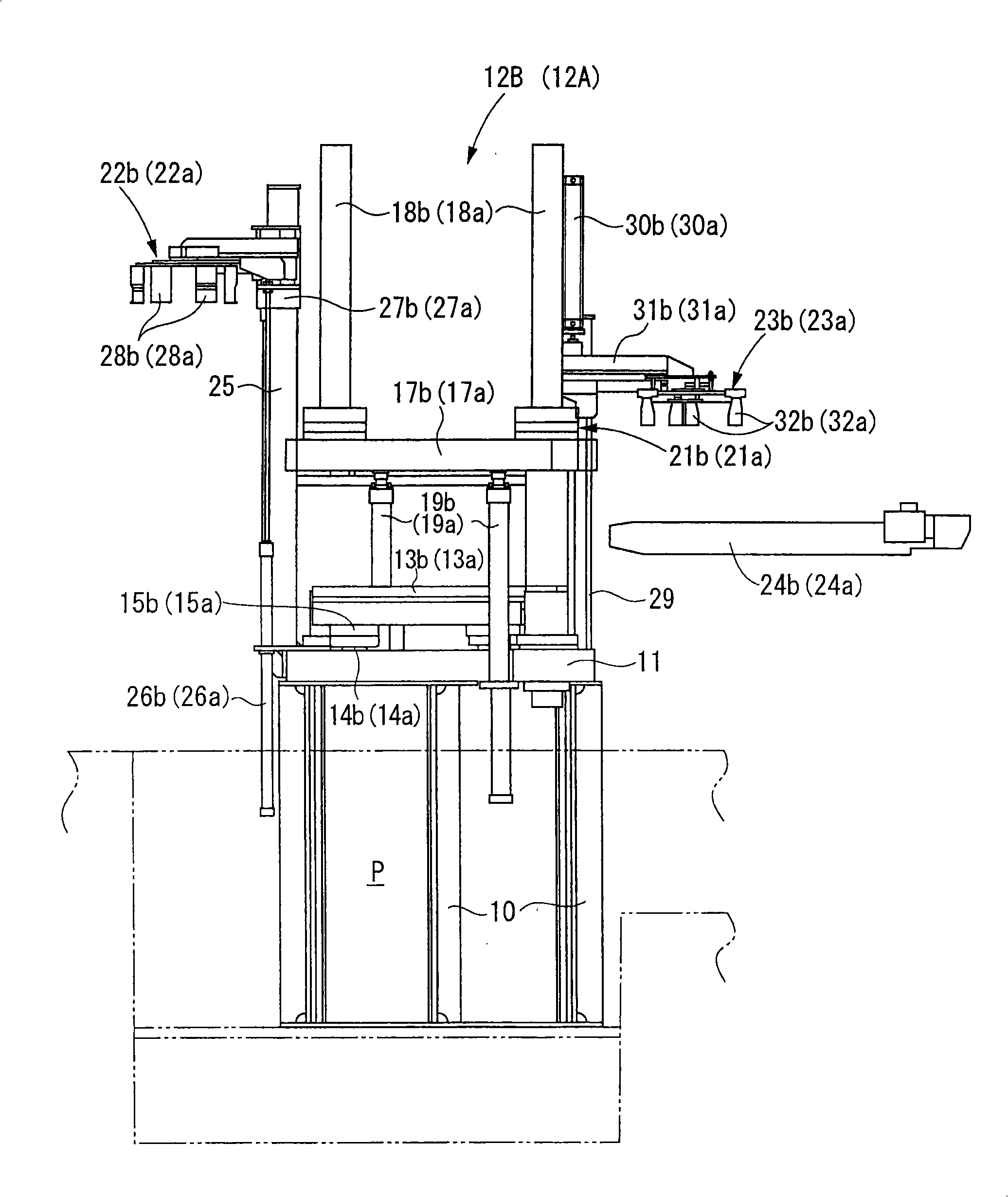
[0052] figure 1 is a front view of a laterally independently operated column equipped curing press showing an embodiment of the present invention. figure 2 is a side view of a laterally independently operated column-equipped press with the upper mold mounting member raised, image 3 is a side view of a laterally independently operated column-equipped press with the upper mold mounting member lowered, Figure 4 It is a plan view of a column-equipped vulcanizing press operated independently laterally.

[0053] As shown in the figure, a base plate 11 is horizontally supported by a plurality of brackets 10 erected in a pit P of a factory, and a left-hand mold opening and closing device 12A and a right-hand mold opening and closing device 12B are mounted on the base plate 11 so as to be operable independently of each other.

[0054] The left-hand mold switch device 12A and the right-hand mold switch device 12B respectively have a lower mold mounting member ( Lower mold supporti...


PUM


Abstract

In a right/left independent action column type vulcanization machine where right/left die opening/closing devices (12A, 12B) supporting upper die fixing members (17a, 17b) corresponding to lower die fixing members (13a, 13b) arranged on a base plate (11) are supported movably up and down by a pair of right/left columns (18a, 18b) standing on the base plate, the pair of right/left columns are arranged in V-shape in plan view between the right/left die opening/closing devices, loaders (22a, 22b) for carrying a green tire (GT) in each die opening/closing device are arranged on the side of columns arranged in V-shape and having a narrow right/left interval, and unloaders (23a, 23b) for carrying a vulcanized tire out of each die opening/closing device are arranged on the side of columns having a wide right/left interval thus making the whole vulcanization machine more compact.

Description


Claims


Application Information

Patent Timeline
Owner MITSUBISHI HEAVY IND MACHINERY SYST LTD
Why Eureka
Try Eureka