
Special self-control power switch for router

A technology for power switches and routers, which is applied in the direction of instruments, electrical components, and adjustment of electrical variables, etc. It can solve the problems that cannot be turned off at once, and achieve the effect of small distance limit

Inactive Publication Date: 2012-07-04
龙启桂
View PDF1 Cites 0 Cited by
  • Summary
  • Abstract
  • Description
  • Claims
  • Application Information

AI Technical Summary

Problems solved by technology

This is still feasible in only one family network, but it cannot be turned off when multiple scattered users share the ROUTER

Method used


Image

  • Special self-control power switch for router
  • Special self-control power switch for router
  • Special self-control power switch for router

Examples


Embodiment Construction

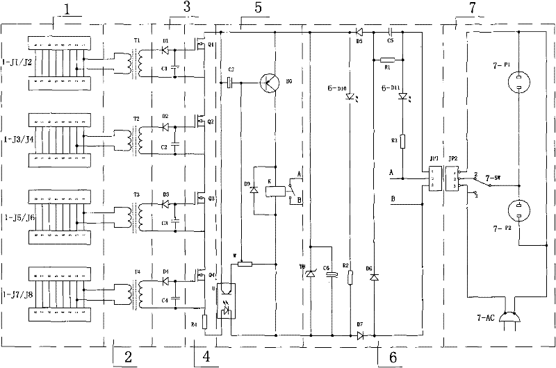
[0015] The present invention will be further described in detail below with reference to the embodiments of the accompanying drawings. figure 2It is a special self-control power switch circuit diagram for routers. Its working principle is (1) The network signal circuit is introduced into the network signal circuit through the RJ45 network cable interface. The specific implementation is that every two RJ45 network cable interfaces are connected in series. In this example, 1-J1 / J2, 1-J3 / J4, 1-J5 / J6, 1-J7 / J8 are 4 pairs respectively. The PC computer network cable in the shared LAN can be inserted into any RJ45 of any pair, and then lead out from the other RJ45 socket of the pair and then plugged into the LAN socket of the ROUTER router. Its purpose is to continue connecting the network cable through two RJ45 interfaces to achieve a bare port, from which the TX+ and TX- of each network cable, namely 1 and 2, can be smoothly drawn out. In the figure, 1-J1 / J2, 1-J3 / J4, 1-J5 / J6, 1-...


PUM


Abstract

The invention relates to a special self-control power switch for a router, in particular to a switch capable of automatically controlling a power by detecting the presence of network cable signals, which aims at solving the defects that a shared router power in a local area network can not realize the automatic control based on the on-line surfing requirements and needs to be powered in an uninterrupted power supply mode all the year. The invention has the following advantages: 1, the switch can carry out automatic power supply in the presence of the on-line surfing signals and automatic power shutoff in case of no signals; 2, the control distance is synchronized with the network cable transmission distance; 3, network signals acquired in a passive isolation coupling mode are used as the automatic signal source and have no intrusion influence on the network; 4,the switch is a network corollary equipment which is completely independent of the network and can realize the automatic control without changing the original operation; and 5, the switch realizes on-demand power utilization, consumption lowering, energy saving and device life extension. The invention realizes the full automatic control of the powers of a router and a modem, and achieves the purposes of electricity saving, money saving and security.

Description

Technical field [0001] The invention relates to local area network matching equipment, which is an automatic control switch for sharing the power supply of local area network equipment such as ROUTER router and MODEM modem HUB hub. Background technique [0002] Nowadays, users who share the network through ROUTER routers and MODEM modems have a common desire, which is the urgent need to solve the automatic power control, because in the case of automatic control, to ensure that all shared users in the LAN can access the Internet at will, it is necessary to provide all-weather power to the shared network equipment. powered by. This also makes the ROUTER router, MODEM modem and two power adapters charged for a long time, especially in the hot summer when they gather together to generate heat, it is really worrying. Although the power consumption of a small router is not large, but it is powered on 24 hours a day. In addition to the indispensable need for Internet access, most ...

Claims


Application Information

Patent Timeline
Patent Type & Authority Patents(China)
IPC IPC(8): H02M3/155H04L12/04
Inventor 龙启桂
Owner 龙启桂
Learn More