
Centering device of engine and dynamometer coupling

A centering device and engine technology, applied in mechanical measuring devices, engine testing, measuring devices, etc.

Inactive Publication Date: 2015-02-04
WUHU MINTAI COPPER IND
View PDF7 Cites 2 Cited by
  • Summary
  • Abstract
  • Description
  • Claims
  • Application Information

AI Technical Summary

Problems solved by technology

The most commonly used method is to make a bracket with one end fixed on the main shaft flange of the dynamometer and the other end fix the dial indicator with a magnetic base. When measuring, turn the dynamometer to adjust the installation position of the engine according to the indication of the dial indicator. This is not only costly, but also inconvenient to operate

Method used


Image

  • Centering device of engine and dynamometer coupling

Examples


Embodiment Construction

[0021] The present invention will be further described below in conjunction with specific embodiments.

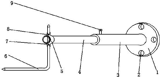
[0022] Such as figure 1 As shown, a centering device for a coupling between an engine and a dynamometer includes a positioning plate 1 , a sleeve 3 , a fixing member 5 and a pointer 6 . The positioning plate 1 is provided with four positioning holes 2, which are respectively located at the left and right ends of the X axis of the positioning plate 1 and the upper and lower ends of the Y axis, so that the fixing plate 1 can be fixed on the dynamometer coupling after alignment. The sleeve 3 is provided with a sleeve 4, one end of the sleeve 3 is fixed at the center of the positioning plate 1, and the other end is movably connected with one end of the sleeve 4, and the extension and contraction of the sleeve 3 and the sleeve 4 assembly make the The distance between the two can be controlled as required, so as to control the distance between the engine and the dynamometer cou...


PUM


Abstract

The invention discloses a centering device of an engine and a dynamometer coupling, and belongs to the field of mechanical centering devices. The device comprises a positioning plate, a sleeve, a fixing part and a pointer; the positioning plate is fixedly connected with the dynamometer coupling; one end of the sleeve is fixed to the center of the positioning plate and while the other end of the sleeve is movably connected with one end of a casing pipe, wherein the casing pipe is arranged in the sleeve; the same through hole is arranged in the same area of the casing pipe and the fixing part; the pointer is arranged in the through hole; the fixing part is fixed to the other end of the casing pipe; a first fixing part bolt and a second fixing part bolt are respectively arranged on the outer surfaces of an upper circular hole and a lower circular hole of the fixing part; a sleeve bolt is arranged at one end of a part in which the sleeve is connected with the casing pipe. The device is simple in structure, reasonable in design and easy to be manufactured; the shortage of small accuracy caused by manual operation is overcome; moreover, the limitation on the distance from the engine to the dynamometer coupling is reduced, and thus the operation is convenient; in addition, the centering of the engines of different specifications applies; therefore, the applicable scope is expanded.

Description

technical field [0001] The invention belongs to the field of mechanical centering devices, and more specifically relates to a centering device for a shaft coupling of an engine and a dynamometer. Background technique [0002] Before there was no centering device for the coupling of the engine and the dynamometer, the centering of the two was mainly a manual operation. The operator's eyes saw that the adjustment was all based on personal experience, and the human factor was large. The dynamometer is connected to the engine through the transmission shaft. Generally, it is impossible for the transmission shaft to match the engine exactly, so a transition flange or other transition devices must be processed. The most commonly used method is to make a bracket with one end fixed on the main shaft flange of the dynamometer and the other end fix the dial indicator with a magnetic base. When measuring, turn the dynamometer to adjust the installation position of the engine according t...

Claims


Application Information

Patent Timeline
Patent Type & Authority Applications(China)
IPC IPC(8): G01M15/02G01B5/00B25B11/00
Inventor 颜承龙
Owner WUHU MINTAI COPPER IND
Learn More