
Air-exhaust decompression-preventing diaphragm type booster pump for spraying

A booster pump and diaphragm type technology, applied in the field of spraying diaphragm booster pumps, can solve the problems of the non-return rubber pad 80 and the drainage seat 71 being unable to be completely sealed, insufficient structural strength, deformation, etc.

Inactive Publication Date: 2010-09-22
蔡应麟 +1
View PDF2 Cites 1 Cited by
  • Summary
  • Abstract
  • Description
  • Claims
  • Application Information

AI Technical Summary

Problems solved by technology

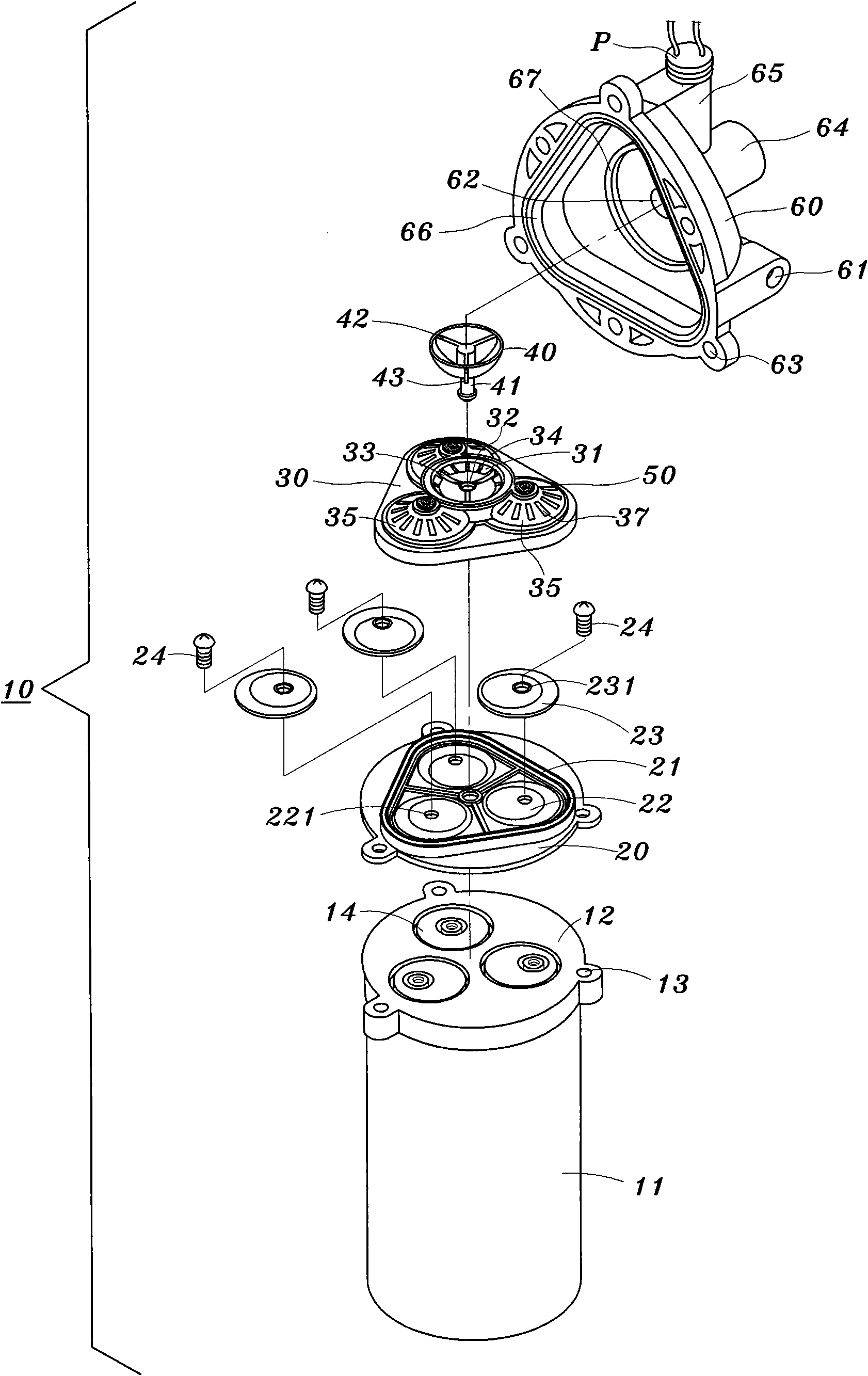
[0013] see Figure 12 As shown, after a long-term actual test and use of the piston valve body 70 and the non-return rubber pad 80, the problem of "loss of pressure" can indeed be greatly improved, and the non-reverse rubber pad 80 will no longer be deformed. However, it is found that after using for a period of time, the T-shaped positioning column 90 will loosen, resulting in the situation that the anti-reverse rubber pad 80 and the drain seat 71 cannot be completely sealed, and the structural strength of each flap in the anti-reverse rubber pad 80 If it is not enough, it may affect the service life of the diaphragm booster pump 10 for spraying; moreover, the original three trumpet-shaped piston pieces 50 will not be affected by factors such as continuous mutual opening and closing actions and material aging. There will be the disadvantage of deformation; therefore, the inventor is actively studying again to improve the two major problems of no pressure loss at all and eliminating the interruption or instability of water pressure caused by air ingress, and has obtained the best solution

Method used


Image

  • Air-exhaust decompression-preventing diaphragm type booster pump for spraying
  • Air-exhaust decompression-preventing diaphragm type booster pump for spraying
  • Air-exhaust decompression-preventing diaphragm type booster pump for spraying

Examples


no. 1 example

[0079] Such as Figure 13 and Figure 14 Shown is the first embodiment of a diaphragm booster pump for spraying that can be exhausted according to the present invention, which includes:

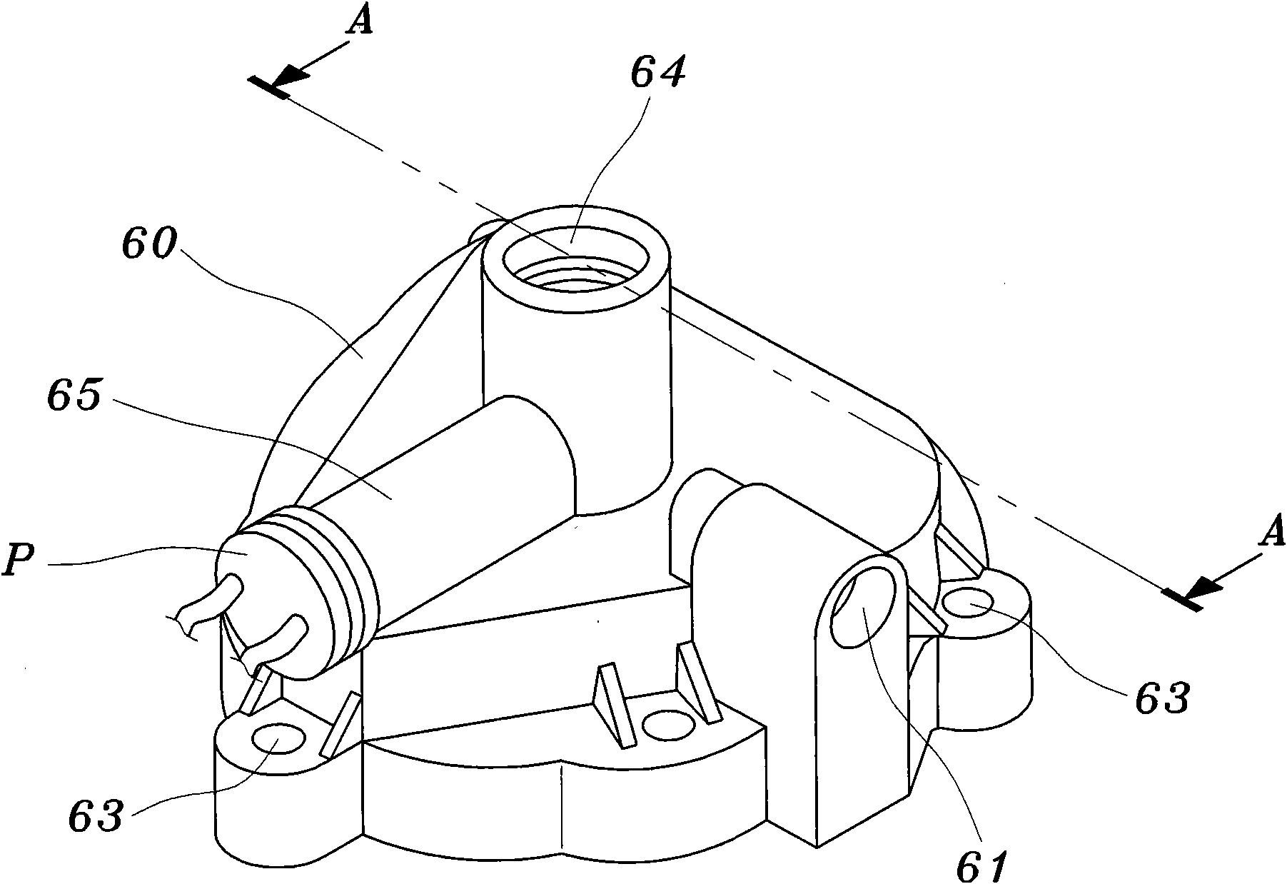
[0080] An exhaust seat 100 is a hollow cylindrical body and is connected to the side wall surface of the outlet pipe seat 64 of the upper pump head cover 60 of the diaphragm type booster pump 10 for spraying. The lower section and the upper section are respectively provided with a first exhaust chamber. 101 and a second exhaust chamber 102, the diameter of the first exhaust chamber 101 is larger than the second exhaust chamber 102 and communicates with each other, and the first exhaust chamber 101 and the outlet pipe seat of the pump head cover 60 A vent 103 is pierced at the junction of the side walls of 64, and a vent 104 is pierced in the center of the top surface of the exhaust seat 100 toward the second exhaust chamber 102; and

[0081] A pneumatic piston seat 200, the top surface is a...


PUM


Abstract

The invention relates to an air-exhaust decompression-preventing diaphragm type booster pump for spraying. A hollow tubular air exhaust seat is directly arranged on the side of the discharging tube seat of pump bonnet, and an air pressure piston seat and a compression spring are arranged in the air exhaust seat, a ventilation port is arranged at the joint of the air exhaust seat and the discharging tube seat, and the central top of the air exhaust seat is provided with a vent hole communicated with the air pressure piston seat in a penetrating way. When air is contained in pressurized water, the pressure of the pressurized water is reduced and elastic force of the compression spring in the air exhaust seat is larger than the pressure of the pressurized water, and the air in the pressurized water can enter the air pressure piston by virtue of the through hole of the air pressure piston tube under the action of the elastic force of the compression spring, and finally the air is discharged outside the pump bonnet by virtue of the vent hole of the air exhaust seat, so as to remove the air in the diaphragm type booster pump for spraying, cause the construction members not to be in unsmooth operation as air is contained and cause the entire output water pressure not to be interrupted or unsteady, and meanwhile the service life thereof can be prolonged.

Description

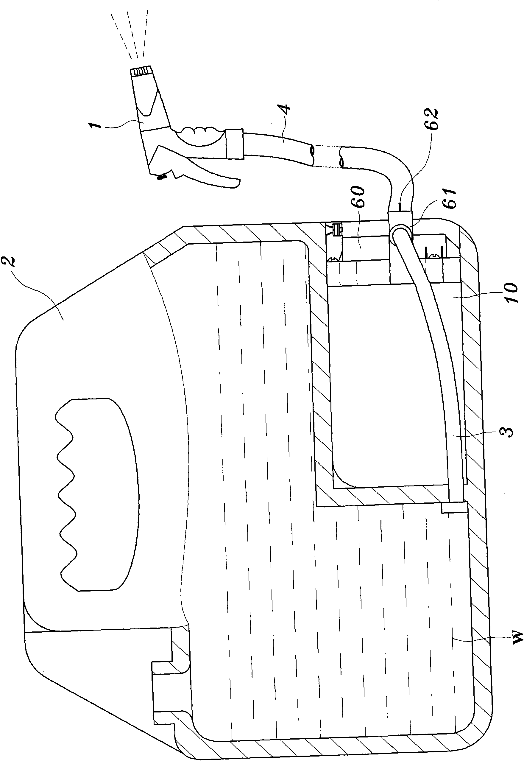
(1) Technical field: [0001] The invention relates to a diaphragm type booster pump for spraying arranged on a pressurized water cleaning appliance, which can provide pressurized water without losing pressure, so that the cleaning appliance can obtain a stable water pressure output, and is particularly beneficial A buff to the effectiveness of water jet cleaning. (two) background technology: [0002] Such as figure 1 As shown, it is a commercially available pressurized cleaning device commonly used for washing automobiles. It is mainly composed of a water spray gun 1, a diaphragm type booster pump 10 for spraying and a portable water storage tank 2. Its advantage is that the spraying The small size of the diaphragm booster pump 10 can be plugged into the portable water storage tank 2, and its power supply is DC 24 volts and can directly utilize the cigarette lighter switch of the car to insert and use, and then use the portable The water storage tank 2 is not limited by the...

Claims


Application Information

Patent Timeline
IPC IPC(8): F04B43/02
Inventor 蔡应麟徐兆火
Owner 蔡应麟
Learn More