
All-optical dispersion monitor based on optical parameter amplifier

An optical amplifier and amplifier technology, which is applied in the fields of instruments, optics, nonlinear optics, etc., can solve the problems of insufficient sensitivity to optical signal dispersion changes, large system power consumption and volume, and low output signal contrast, and achieve signal rate and modulation format The effects of transparency, high output signal contrast, and wide working band

Inactive Publication Date: 2010-09-22
HUAZHONG UNIV OF SCI & TECH
View PDF0 Cites 18 Cited by
  • Summary
  • Abstract
  • Description
  • Claims
  • Application Information

AI Technical Summary

Benefits of technology

The technology described by this inventor allows for better transmission speed with less distortion than previous methods like AM or FM signals while still maintaining good quality images captured through lens-based cameras.

Problems solved by technology

Technological Problem addressed in this patented technical solution describes various issues related to achieving accurate measurement over wide ranges of CD's speeds without increasing complexity or requiring expensive equipment. Current solutions involve either advanced receivers that use coherdetering detectors or interferometric disperse compensators (IDDC). Optical Dispersity Monitoring (OMDA)-based approaches suffer limitations including slow responsiveness, sensitivity to environmental factors like temperature variation, difficulty in tuning the refractive index balance between different components, and limited data transfer capabilities.

Method used


Image

  • All-optical dispersion monitor based on optical parameter amplifier
  • All-optical dispersion monitor based on optical parameter amplifier
  • All-optical dispersion monitor based on optical parameter amplifier

Examples


Embodiment Construction

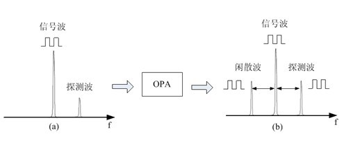
[0020] Such as figure 1 The all-optical dispersion monitor shown includes: the input tunable optical filter TF, the optical amplifier is an erbium-doped fiber amplifier EDFA, and the optical amplifier can also use SOA or other optical amplifiers, such as semiconductor optical amplifiers, where the required signal power is low The optical amplifier can also be omitted; the semiconductor laser LD that provides continuous detection waves, the optical parametric amplifier OPA, the output optical filter Filter and the optical power meter. After the wavelength division multiplexing WDM optical signal passes through the optical coupler Coupler, most of the optical power is transmitted along the original path, and a small part of the optical power enters the all-optical dispersion monitor shown in the dashed box. TF controls the wavelength of the WDM signal input to the dispersion monitoring system. By adjusting the central wavelength of the TF, WDM channels can enter the dispersion m...


PUM


Abstract

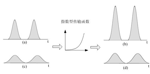
The invention relates to an all-optical dispersion monitor based on an optical parameter amplifier. The all-optical dispersion monitor comprises a semiconductor laser, a coupler, the optical parameter amplifier, an output optical filter and an optical power meter. The semiconductor laser emits low-power continuous detection light. The continuous detection light and signal light are combined through the coupler and are filled into the optical parameter amplifier. The optical parameter amplifier is based on first-order four-wave mixing effect which causes energy to be transferred to detection waves and idle waves from the signal light. The detection waves and the idle waves with exponential gains are output, pass through the output optical filter and are measured by the optical power meter. The invention has the advantages that the response speed is fast, the sensitivity is high, the working waveband is wide, the signal rate and the modulation format are transparent, the monitor can be used for the dispersion monitoring of a WDM system with single channel rate above 100Gb/s, the high-speed photoelectric device and the signal processing circuit are not required during measurement, and the cost of devices is reduced.

Description


Claims


Application Information

Patent Timeline
Owner HUAZHONG UNIV OF SCI & TECH
Learn More