Illuminating device and image display device

A technology for image display devices and lighting devices, applied in lighting devices, lighting devices, independent lighting devices, etc., can solve the problems of insufficient light, inability to obtain sufficient indirect lighting effects, and inability to obtain sufficient indirect lighting to achieve a strong sense of presence Effect

Inactive Publication Date: 2010-09-22
SHARP KK
View PDF1 Cites 4 Cited by
  • Summary
  • Abstract
  • Description
  • Claims
  • Application Information

AI Technical Summary

Problems solved by technology

[0006] However, since the illuminating device 301 disclosed in the above-mentioned Patent Document 1 illuminates the rear wall W only from the downward direction obliquely upward, it cannot sufficiently illuminate the periphery of the screen of the image display device 300, and there is a possibility that the indirect lighting effect cannot be obtained sufficiently. (presence and / or glare mitigation) issues
In particular, there is a problem of insufficient illumination in the horizontal direction of the screen
[0007] In addition, in recent years, image display devices have developed toward larger screens. When lighting devices are applied to large-screen display devices, only the rear wall is illuminated from below, so that the amount of light irradiated on the wall above the screen is insufficient. The effect of indirect lighting cannot be fully obtained

Method used


Image

  • Illuminating device and image display device
  • Illuminating device and image display device
  • Illuminating device and image display device

Examples


no. 1 approach

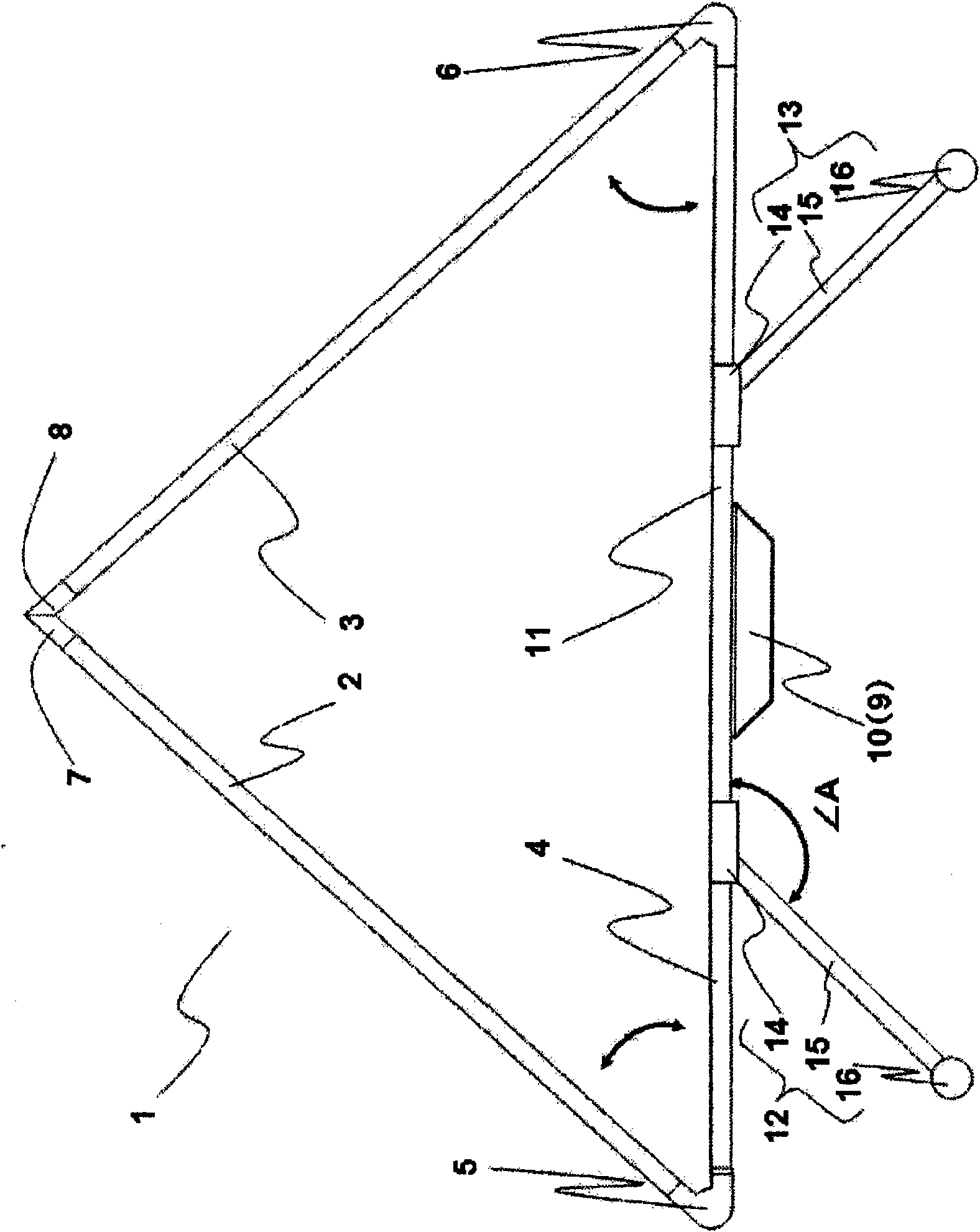
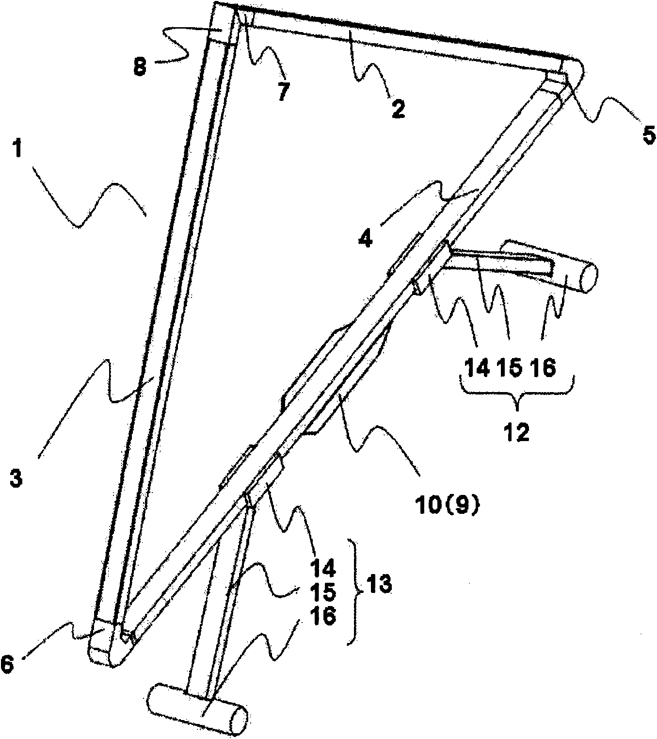
[0102] figure 1 It is a schematic front view of the lighting device 1 according to the first embodiment of the present invention. figure 2 It is a schematic perspective view of the lighting device 1 according to the first embodiment of the present invention.

[0103] The lighting device 1 includes; a first lighting part 2 and a second lighting part 3, which have light emitting diodes (hereinafter referred to as LEDs) as light sources; 2. Lighting Department 3. The support portion 4 is in the shape of a square column made of aluminum, and the first lighting unit 2 and the second lighting unit 3 have a shape in which a part of the inside of the square column made of aluminum is removed for arranging LEDs. The configuration of the first lighting unit 2 and the second lighting unit 3 will be described in detail later.

[0104] Both ends of the supporting part 4 are provided with a first rotating part 5 and a second rotating part 6 which respectively rotate the first illuminat...

no. 2 approach

[0147] Next, a lighting device 41 according to a second embodiment of the present invention will be described with reference to the drawings. Hereinafter, the same parts as those of the first embodiment are assigned the same reference numerals in the drawings, and descriptions thereof are omitted, and the characteristic parts of the second embodiment will be described below.

[0148] Figure 10 It is a schematic front view of the lighting main body 42 of the lighting device 41 according to the second embodiment of the present invention. Figure 11 It is a schematic perspective view of the lighting main body part 42 of the lighting device 41 which concerns on the 2nd Embodiment of this invention.

[0149] Different from the first embodiment that can rotate in only one direction relative to the support part around the first rotating part and the second rotating part respectively, the first lighting part 43 and the second lighting part 43 of the lighting device 41 in the second ...

no. 3 approach

[0157] Next, a lighting device 61 according to a third embodiment of the present invention will be described with reference to the drawings. The parts that are the same as those in the first embodiment or the second embodiment are given the same reference numerals and descriptions thereof are omitted, and the characteristic parts of the third embodiment will be described below.

[0158] Figure 13 It is a schematic front view of the lighting main body part 62 of the lighting device 61 which concerns on the 3rd Embodiment of this invention. Figure 14 It is a schematic perspective view of the lighting main body part 62 of the lighting device 61 which concerns on the 3rd Embodiment of this invention. Figure 15 It is a schematic enlarged view of the rotation mechanism of the lighting device 61 according to the third embodiment of the present invention.

[0159] The lighting device 61 of the third embodiment has a rotating mechanism capable of rotating in multiple directions, a...


PUM


Abstract

A conventional illuminating device cannot sufficiently illuminate the periphery of the screen of an image display device, and effects of indirect illumination (reality or glare reduction) cannot be obtained sufficiently. In particular, illuminance to the transverse direction of the screen is not sufficient. The illuminating device of this invention, which illuminates the periphery of a device such as the image display device, has a plurality of illumination parts loaded with light sources and a supporting part which supports the illumination parts so that lights from the illumination parts respectively illuminate different areas of the periphery of the device.

Description

technical field [0001] The present invention relates to an illumination device for illuminating the surroundings of equipment such as an image display device, and an image display device having the same. Background technique [0002] In recent years, due to the high performance of image display devices such as liquid crystal display devices and EL (electroluminescent) display devices, and the development of digital broadcast technology, broadcast and transmission technologies have been developed, and an environment for viewing high-quality images has been provided. [0003] In addition, as one of the methods for watching video such as movies with enhanced sense of presence, it is to reduce the illumination brightness (illuminance) of the room where the image display device is installed. In the case of viewing by reducing the illuminance of the room lighting, generally by lighting the surroundings of the image display device, you can feel a stronger sense of presence when wat...

Claims


Application Information

Patent Timeline
Patent Type & Authority Applications(China)
IPC IPC(8): F21S2/00F21S6/00F21V21/26F21Y101/02
CPCF21S6/004G06F1/1607F21V33/0052H04N9/315
Inventor 高桥富志雄金子毅若林保孝松实孝友
Owner SHARP KK
Why Eureka
Try Eureka