Data transmission device, method for transmitting data, audio-visual environment control device, audio-visual environment control system, and method for controlling audio-visual environment

A technology of a data sending device and a data sending method, which can be applied to two-way working systems, televisions, selective content distribution, etc., and can solve problems such as inability to control lighting

Inactive Publication Date: 2011-06-08
SHARP KK
View PDF1 Cites 2 Cited by
  • Summary
  • Abstract
  • Description
  • Claims
  • Application Information

AI Technical Summary

Problems solved by technology

However, this lighting control data is only lighting control data corresponding to the predetermined distribution of lighting devices (installation positions of lighting devices in the virtual audio-visual environment space), and there is a problem that it is impossible to assign different configurations of lighting devices to each user. to the problem of proper lighting control

Method used


Image

  • Data transmission device, method for transmitting data, audio-visual environment control device, audio-visual environment control system, and method for controlling audio-visual environment
  • Data transmission device, method for transmitting data, audio-visual environment control device, audio-visual environment control system, and method for controlling audio-visual environment
  • Data transmission device, method for transmitting data, audio-visual environment control device, audio-visual environment control system, and method for controlling audio-visual environment

Examples


Embodiment approach 1

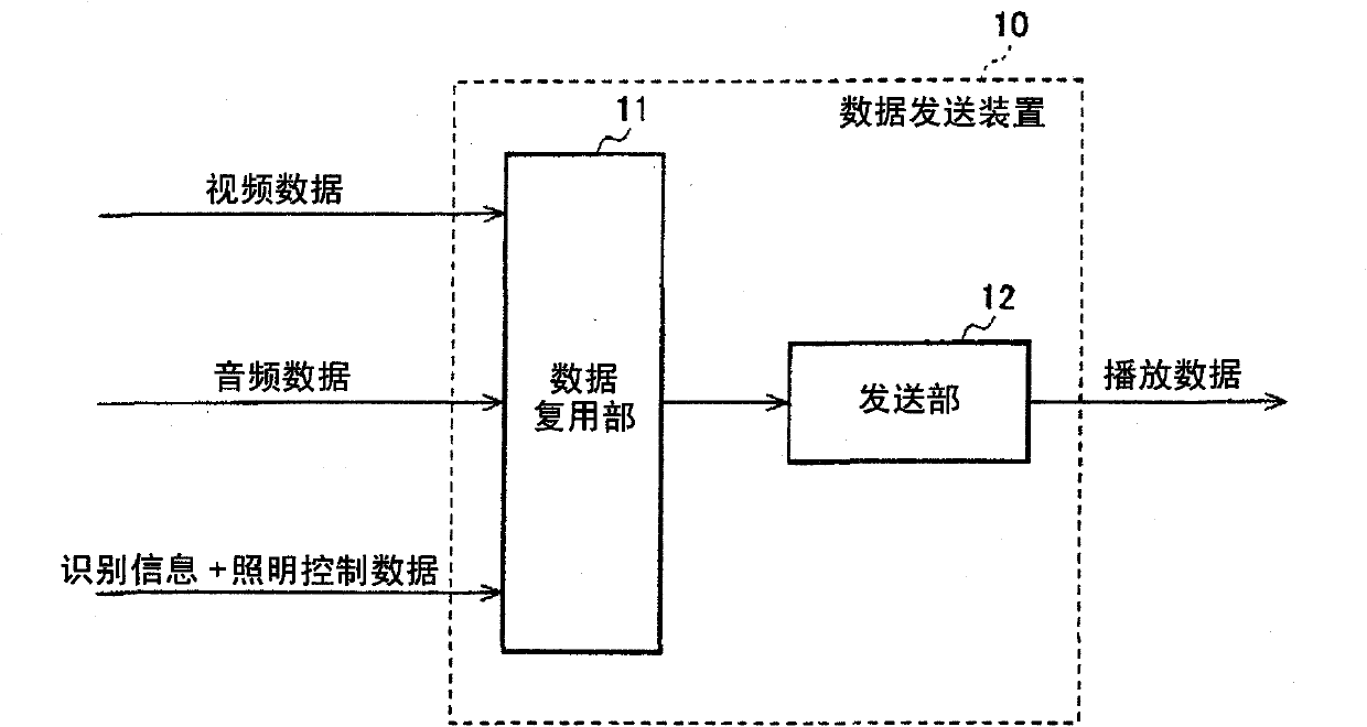
[0061] figure 1 It is a block diagram showing a schematic configuration example of a data transmission device according to an embodiment of the present invention.

[0062] The data transmission device 10 in this embodiment is composed of a data multiplexing unit 11 and a transmission unit 12 .

[0063] The input video data is compressed and encoded, and output to the data multiplexing unit 11 . Various compression methods such as ISO / IEC 13818-2 (MPEG-2Video), ISO / IEC 14496-2 (MPEG-4 Visual), and ISO / IEC 14496-10 (MPEG-4 AVC) can be used for video encoding.

[0064] Similarly, the input audio data is compressed and encoded, and output to the data multiplexing unit 11 . Various compression methods such as ISO / IEC 13818-7 (MPEG-2 AAC) and ISO / IEC 14496-3 (MPEG-4 Audio) can be used for audio coding.

[0065] Furthermore, the identification information and lighting control data are compressed and coded, and output to the data multiplexing unit 11 . In addition, the identificat...

Embodiment approach 2

[0120] A second embodiment of the present invention will be described with reference to the drawings. Since the schematic structures of the data sending device and the data receiving device in this embodiment are consistent with figure 1 and Figure 7 are the same, so detailed description is omitted.

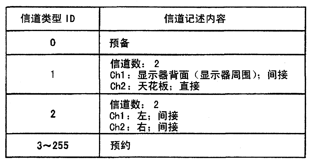
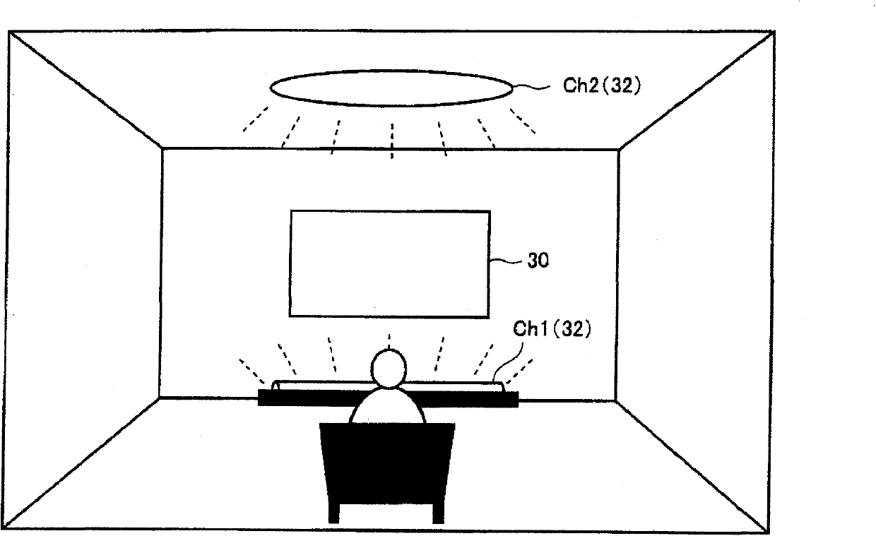
[0121] First, an example of a lighting device will be described. Figure 14 It is a diagram showing the structure of a table referred to when describing the arrangement pattern of a plurality of lighting devices and the position of each lighting device. The reference table is composed of a first table ( T16 ) indicating the arrangement pattern of the lighting devices in the audio-visual environment space, and a second table ( T16 a , T16 b , T16 c , T16 d ) showing the positions of the lighting devices.

[0122] The data transmission device 10 transmits the value (ChannelTypeID) indicating the lighting arrangement pattern, the value (Position) indicating the position of each ...

Embodiment approach 3

[0135] A third embodiment of the present invention will be described with reference to the drawings. Figure 20 It is a figure which shows another structural example of the table referred to when describing the position of each peripheral device. The reference table is composed of a first table specifying "left", "right", and "front" positions (Position), and a second table specifying a list of available positions and a detailed arrangement of each available position. Figure 20 The definition of Position in the first table is an example, and the positions included in the specific wall surface of the audio-visual environment space may be uniformly defined as surfaces such as "left side", "right side", and "front side". For example, the front left, left, and rear left in the first table can also be collectively defined as the left face, or the front right, right, and rear right in the first table can be collectively defined as the right face.

[0136] The detailed configuratio...


PUM


Abstract

Provided are a data transmission device, a method for transmitting data, an audio-video environment control device, a method for controlling audio-visual environment, an audio-video environment control system, wherein peripheral devices can be appropriately controlled in accordance with the layout of the peripheral devices in an actual audio-visual environment so that a high realistic sensation is obtained. A data reception device (20) receives a predetermined video data and/or audio data, identification information indicative of an arrangement pattern of peripheral devices (lighting devices) arranged in a virtual audio-visual environment space, lighting control data corresponding to the peripheral devices arranged in the virtual audio-visual environment space. A lighting dimming data generation unit generates driving control data for driving and controlling an actual lighting device (32) in accordance with identification information, lighting control data, and arrangement information of the lighting device (32) in an actual audio-visual environment space, wherein the arrangement information is acquired from a lighting arrangement information memory unit (25).

Description

technical field [0001] The present invention relates to a data transmission device, a data transmission method, an audio-visual environment control device, an audio-visual environment control system, and an audio-visual environment control method, and in particular to an audio-visual environment for controlling a user's audio-visual environment for viewing and listening to video / audio content with a strong sense of presence A data transmission device, a data transmission method, an audio-visual environment control device, an audio-visual environment control system, and an audio-visual environment control method for peripheral equipment in space. Background technique [0002] In recent years, with the rapid advancement of video / audio-related electronic technologies, displays have been enlarged, wide-viewed, and high-definition, and surround-sound systems have been improved, making it possible to enjoy immersive video or audio. For example, in the home theater system that is c...

Claims


Application Information

Patent Timeline
Patent Type & Authority Applications(China)
IPC IPC(8): H04N7/14H04N7/24
CPCH04N21/8173H04N21/8133H04N21/42202H04N21/235H04N21/4131H04N21/435H04N21/8186H04N21/4345H04N7/173
Inventor 岩波琢也德毛靖昭荻泽义昭伊藤典男渡部秀一长谷川伸也吉井隆司
Owner SHARP KK
Why Eureka
Try Eureka