SMA radio frequency coaxial connector

A RF coaxial and connector technology, applied in the direction of connection, two-part connection device, contact parts, etc., can solve the application limitations of SMA RF coaxial connectors, the relative displacement of parts is prone to occur, and the product delivery cycle is prolonged. Excellent electrical performance, small discontinuities, improved mechanical reliability

Inactive Publication Date: 2012-08-15
SHANGHAI TUYUE ELECTRONICS CO LTD
View PDF0 Cites 0 Cited by
  • Summary
  • Abstract
  • Description
  • Claims
  • Application Information

AI Technical Summary

Problems solved by technology

[0007] 1) Potting with gelling medium needs to be cured for a long time in a standard temperature and humidity environment, which will prolong the delivery cycle of the product;
[0008] 2) Before filling with gelling medium, it is necessary to position the interface of each part. During the curing process, each part is prone to relative displacement, and secondary positioning is required. Therefore, the product assembly process is cumbersome and the consistency is poor. The interface of the finished product needs to be 100 times. % test;
[0009] 3) Since the softening temperature of the gelling medium is lower than the normal operating temperature of polytetrafluoroethylene, its reliability will decrease in high and low temperature environments, which makes the application of the existing SMA radio frequency coaxial connectors under the temperature shock environment limited. limit;
[0010] 4) Potting with gel medium will form a through hole on the outer conductor, resulting in a large radio frequency leakage

Method used


Image

  • SMA radio frequency coaxial connector
  • SMA radio frequency coaxial connector
  • SMA radio frequency coaxial connector

Examples


Embodiment Construction

[0029] The embodiments of the present invention will be described in further detail below in conjunction with the accompanying drawings, but the present embodiments are not intended to limit the present invention, and any similar structures and similar changes of the present invention should be included in the protection scope of the present invention.

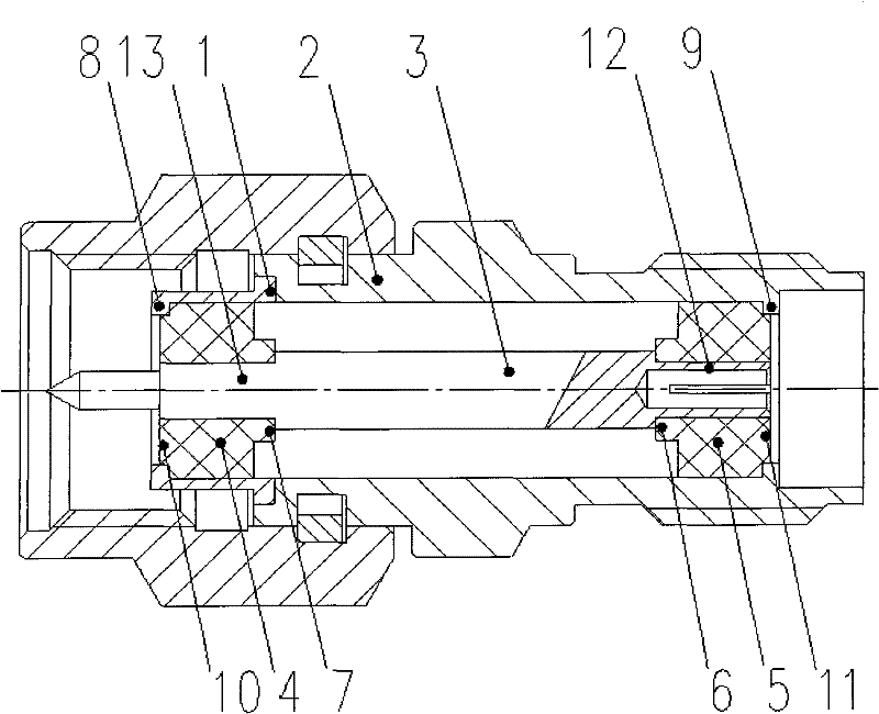
[0030] Such as figure 1 As shown, an SMA radio frequency coaxial connector provided by the embodiment of the present invention includes a left support 4, a right support 5, an outer conductor and an inner conductor 3;

[0031] The outer conductor is provided with an inner cavity with openings at both ends, and is composed of a left outer conductor 1 and a right outer conductor 2, and the right end of the left outer conductor 1 is joined to the left end of the right outer conductor 2;

[0032] The left support 4, the right support 5 and the inner conductor 3 are all arranged in the inner cavity of the outer conductor, and the ...


PUM


Abstract

The invention discloses an SMA radio frequency coaxial connector, relating to the technical field of coaxial connectors and aiming to promote the electric characteristics and the mechanical reliability and reduce contact resistance and radio frequency leakage. The connector comprises a left support, a right support, an outer conductor and an inner conductor, wherein the outer conductor is formed by jointing a left outer conductor with a right outer conductor, and the right end of the left outer conductor is jointed with the left end of the right outer conductor; the left support, the right support and the inner conductor are all fixed in an inner cavity of the outer conductor; the left support and the right support are respectively sleeved at the left end and the right end of the inner conductor, the left end and the right end of the left support are respectively arranged against the left end inner wall of the left outer conductor and the inner conductor, and the left end and the right end of the right support are respectively arranged against the inner conductor and the right end inner wall of the right support; a radial inward boss is arranged on the left end inner wall of the left outer conductor, and a radial inward boss is arranged on the right end inner wall of the right outer conductor. The connector has little radio frequency leakage in the process of matching use.

Description

technical field [0001] The invention relates to the technology of coaxial connectors, in particular to the technology of SMA radio frequency coaxial connectors. Background technique [0002] At present, with the rapid development of the application of RF and microwave technology, the demand for RF coaxial connectors, which act as a bridge for the signal transmission of RF and microwave components, continues to grow rapidly, among which SMA RF coaxial connectors occupy the vast majority of the market share. The leading position of various RF coaxial connectors. In order to adapt to changes in the product application environment, it is particularly important to improve the inherent deficiencies of the SMA RF coaxial connector, and to redesign its design structure that cannot meet the current use environment. [0003] For pairing use, SMA RF coaxial connectors are designed with one end as SMA-K (female) and the other end as SMA-J (male). [0004] Such as Figure 4 As shown, i...

Claims


Application Information

Patent Timeline
Patent Type & Authority Patents(China)
IPC IPC(8): H01R24/40H01R13/46H01R13/20H01R13/40
Inventor 王云胜
Owner SHANGHAI TUYUE ELECTRONICS CO LTD
Why Eureka
Try Eureka