
Metal wire clipper

A shearer and metal wire technology, applied in the shearer field, can solve problems such as inability to obtain support effects and poor shearing.

Inactive Publication Date: 2010-10-06
ALLPROFESSIONAL MFG
View PDF1 Cites 8 Cited by
  • Summary
  • Abstract
  • Description
  • Claims
  • Application Information

AI Technical Summary

Problems solved by technology

[0003] However, the existing design method has been used for a long time, and the aforementioned metal scissors still have the disadvantage of not being able to cut well when cutting. Playing the best applied force enables the metal shears to produce the maximum applied force in an instant. Therefore, it is necessary to study and solve the problems of the prior art in order to devote ourselves to

Method used


Image

  • Metal wire clipper
  • Metal wire clipper
  • Metal wire clipper

Examples


Embodiment Construction

[0020] Regarding the technology, means and effects used in the present invention, a preferred embodiment is given and described in detail below with drawings, which are for illustration purposes only, and are not limited by this structure in the patent application.

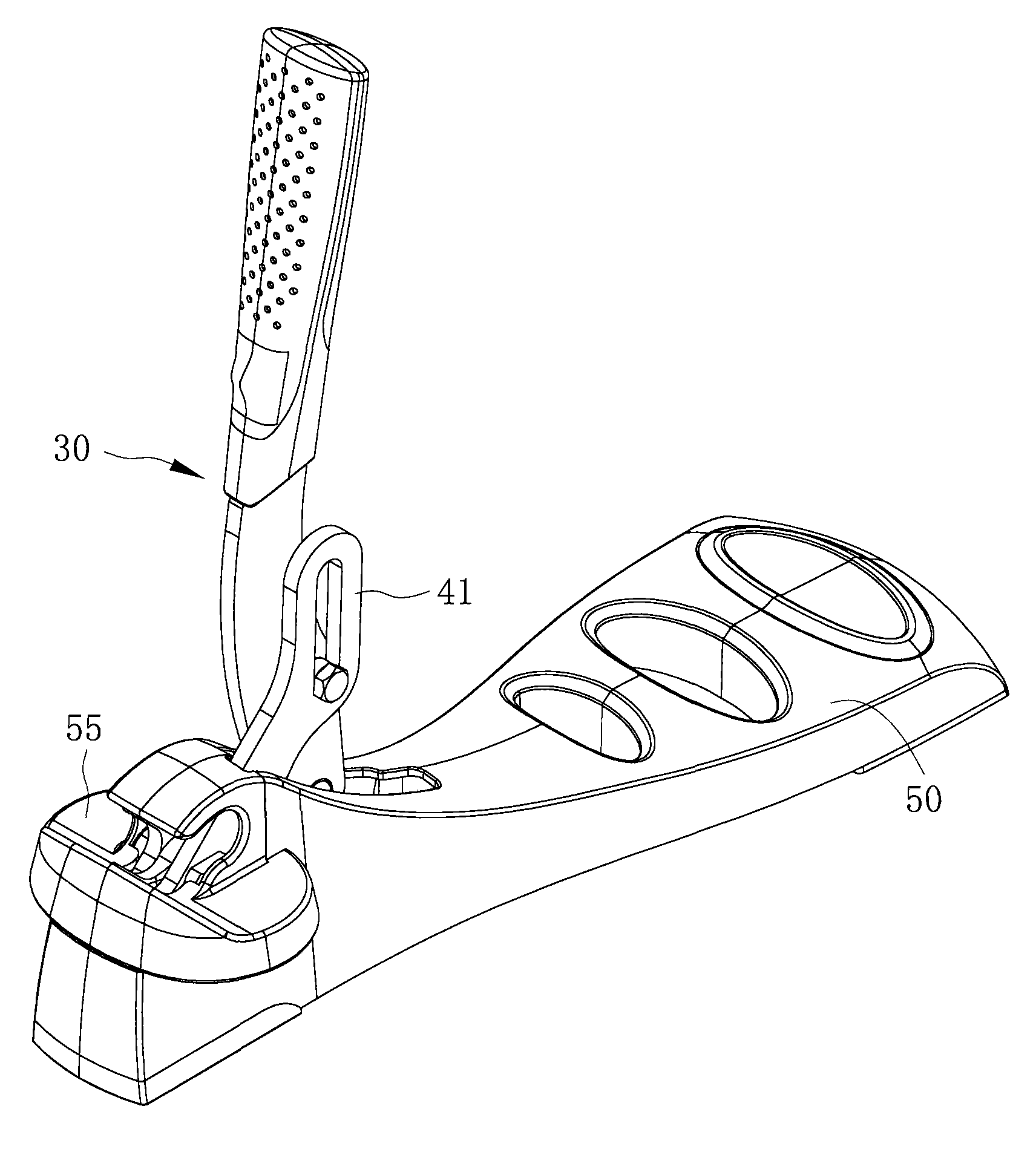
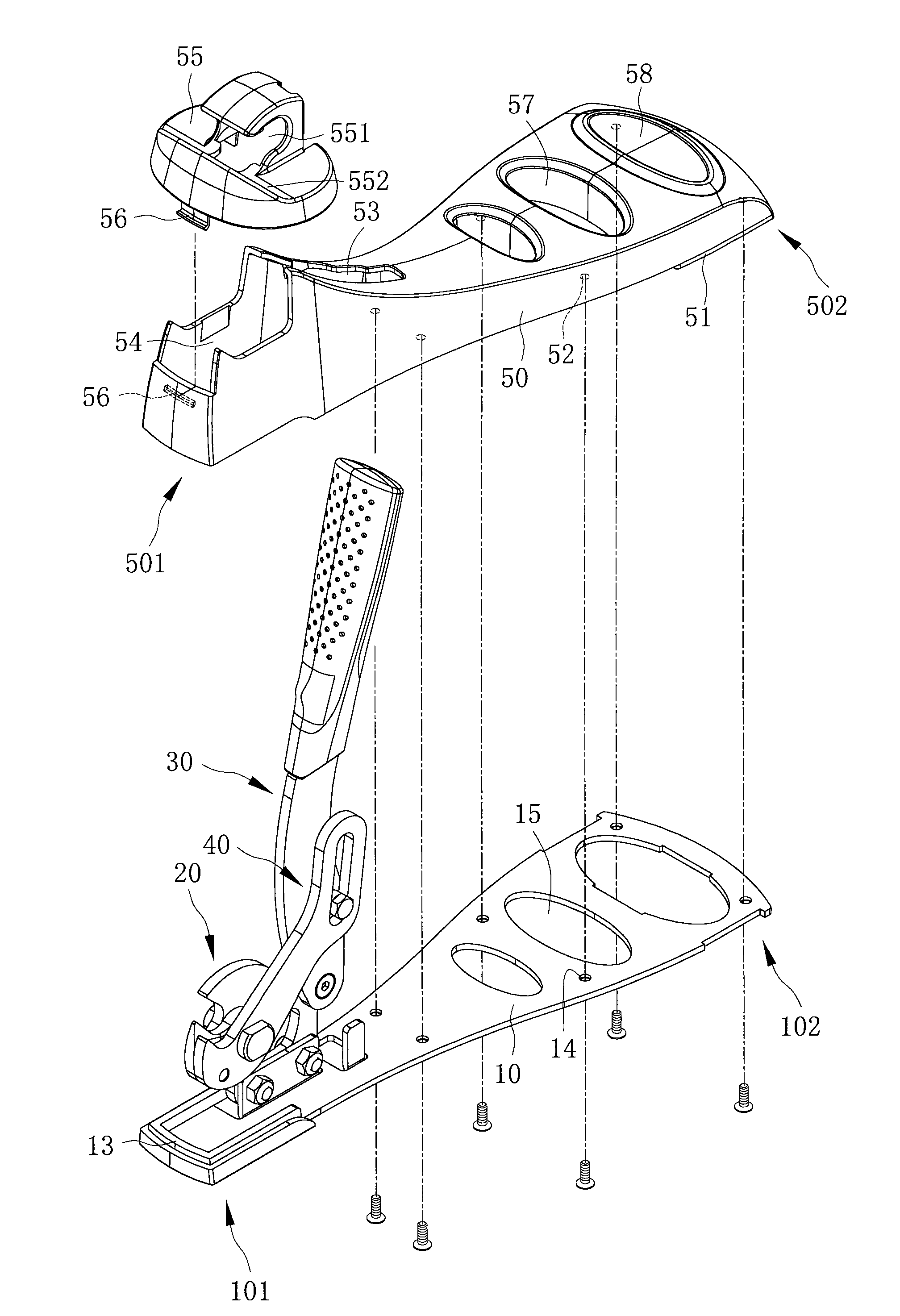
[0021] refer to figure 1 and figure 2 , is a three-dimensional appearance view and a three-dimensional exploded view of the metal wire cutter of the present invention. The present invention includes a base 10 , a knife holder 20 , a pressing handle 30 , a blade body 40 and a cover body 50 .

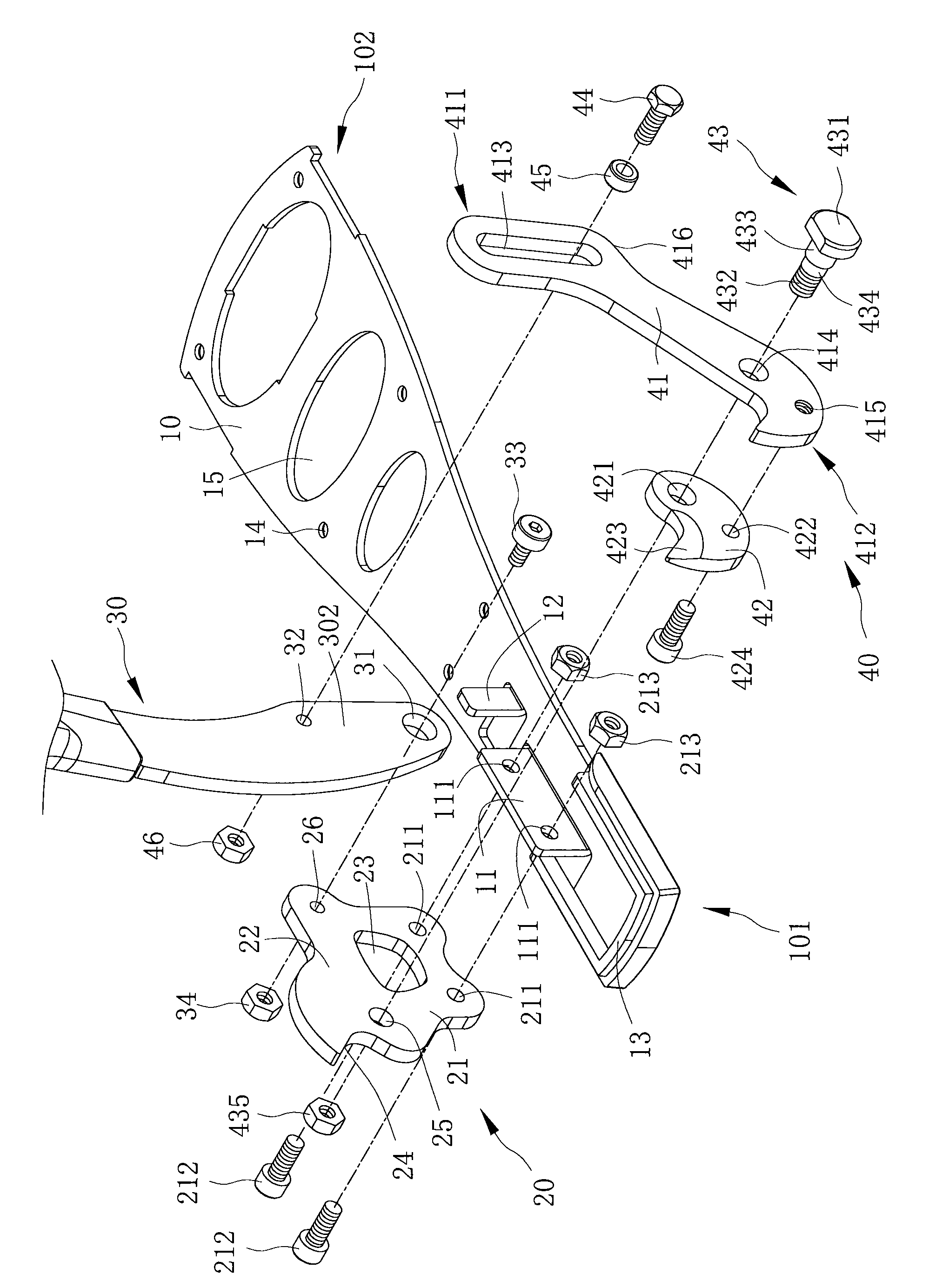
[0022] Also refer to image 3 and Figure 4 , the base 10 can be placed on a plane, the base 10 has a first end 101 and a second end 102, the first end 101 is protruded with a joint portion 11 and a stop portion 12, the joint portion 11 and the The blocking portion 12 is formed by bending a part of the base 10 , and the blocking portion 12 is disposed between the combining portion 11 and the second end 102 of the base 10...


PUM


Abstract

The invention relates to a metal wire clipper. The clipper comprises a base, a cutter seat, a pressing handle and a blade body, wherein the base can be placed on a plane; the cutter seat is fixed on the base, the cutter seat is provided with a first pivot part and second pivot part; the hinge joint end of the pressing handle is pivoted on the second pivot part, the two ends of the blade body separately form an adjusting hole and a blade part; the blade part is pivoted on the first pivot part, and the adjusting hole is pivoted between the two ends of the pressing handle through a pivoting part so that the grab handle is linked with the blade part of the blade body and the cutter seat, the base is steady placed on the plane and the grab handle is easy to press and drive the blade body for cutting.

Description

technical field [0001] The invention relates to a cutter, in particular to a metal wire cutter which can be stably supported on a plane. Background technique [0002] Referring to the Patent No. CN 2242750 of the People's Republic of China "Improved Structure of Metal Scissors", it consists of a clip-off group, a toggle group and a pair of handles. It is characterized in that an adjustment member is provided between the first and second toggles, one end of the adjustment member is pivotally arranged on a predetermined position of the first toggle, and the other end of the adjustment member is capable of reciprocating movement in a predetermined direction. It is arranged on a predetermined position of the second toggle, and the second toggle is provided with an adjustment button that can change the relative position of the adjustment member and the second toggle in a rotational manner. The user can change the included angle between the first and second blades on the first an...

Claims


Application Information

Patent Timeline
IPC IPC(8): B23D29/02B21F11/00
Inventor 黄信德
Owner ALLPROFESSIONAL MFG
Learn More