Mobile monitoring system and monitoring terminal thereof

A monitoring terminal and mobile monitoring technology, applied in closed-circuit television systems, telephone communications, electrical components, etc., can solve problems such as inability to see real-time conditions, incomplete functions, and inability to control the monitored site

Inactive Publication Date: 2010-10-06
深圳市鼎盛威电子有限公司
View PDF3 Cites 42 Cited by
  • Summary
  • Abstract
  • Description
  • Claims
  • Application Information

AI Technical Summary

Problems solved by technology

[0002] The existing traditional monitoring terminals are generally placed in a fixed position, so the following disadvantages will appear: when the object or place to be monitored is a moving object or place, the specific location to be monitored cannot be determined, and the monitored real-time video and sound cannot be seen Understand the real-time situation and cannot control the monitored site. At the same time, when the monitoring terminal equipment is damaged, it cannot be used for subsequent information calls
[0005] The above-mentioned existing mobile monitoring technology can realize basic mobile monitoring functions, but most functions are limited to data transmission between terminals and platforms, such as transmitting pictures taken on the spot to the platform or the monitoring party through a wireless module, or transferring the terminal’s The location and alarm information are notified to the monitoring party through text messages. These methods are inevitably prone to information delays, especially when only one wireless module is used for data transmission and voice playback; and the incomplete functions lead to existing functions in actual use It cannot fully function, such as it cannot be adjusted in real time according to the needs of users, and at the same time, when the monitoring terminal equipment is damaged, it cannot be used for subsequent information calls

Method used


Image

  • Mobile monitoring system and monitoring terminal thereof
  • Mobile monitoring system and monitoring terminal thereof
  • Mobile monitoring system and monitoring terminal thereof

Examples


Embodiment Construction

[0020] In order to describe the technical content, structural features, achieved goals and effects of the present invention in detail, the following will be described in detail in conjunction with the embodiments and accompanying drawings.

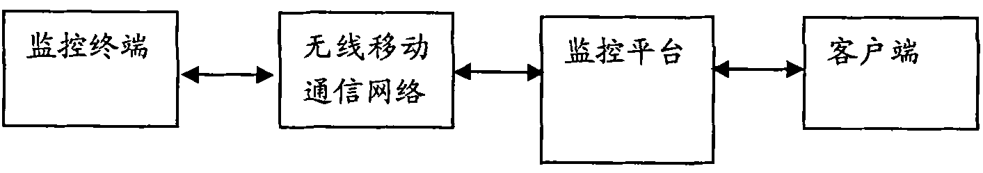
[0021] see figure 1 as well as figure 2 , the embodiment of the mobile monitoring system of the present invention includes a monitoring terminal, a monitoring platform, and a client;

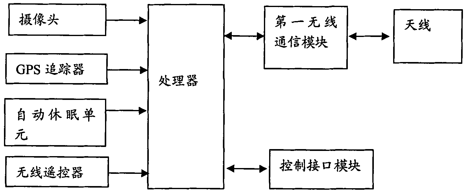
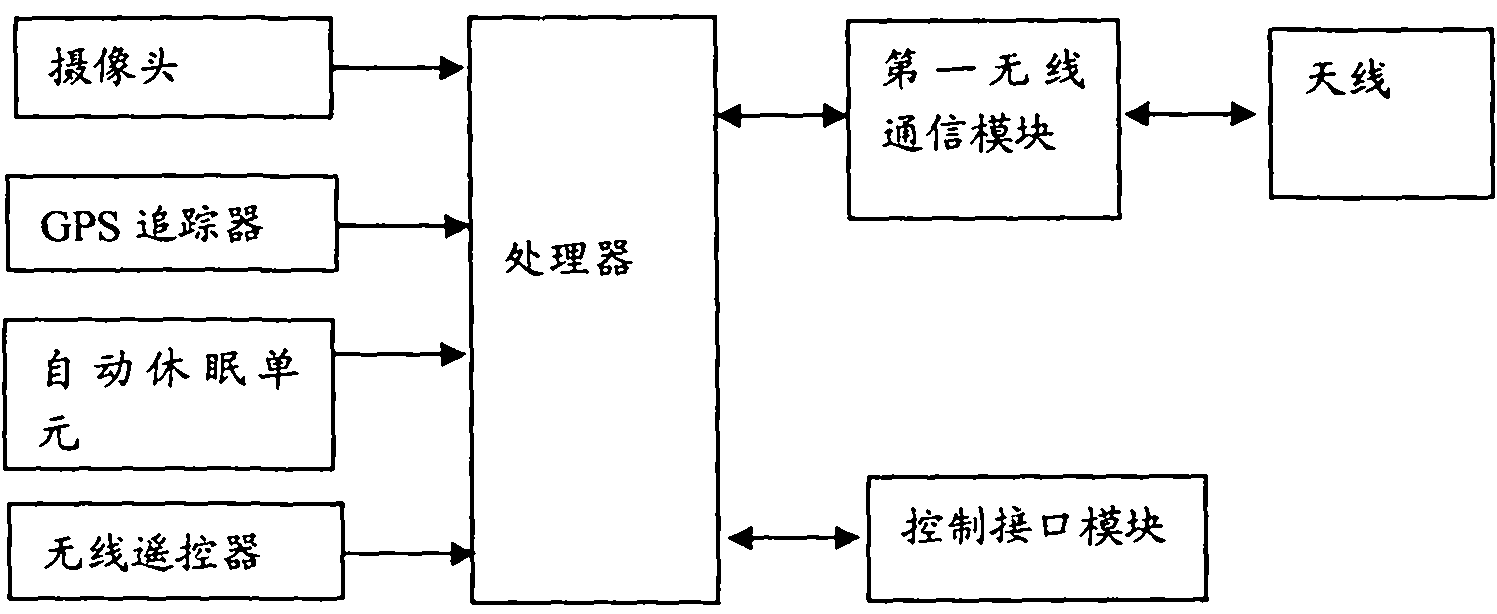
[0022] The monitoring terminal includes a processor and a camera connected to the processor, a GPS tracker, a wireless remote controller, a first wireless communication module, a sound pickup and a control interface;

[0023] The camera is used to shoot real-time video or images;

[0024] The GPS tracker includes a GPS module and a second wireless communication module interconnected and both connected to the processor;

[0025] The processor includes:

[0026] The positioning module is used to immediately trigger the GPS module to perform positioning or...


PUM


Abstract

The invention discloses a mobile monitoring system and a monitoring terminal thereof. The terminal comprises a processor and a camera, a GPS tracker, a wireless remote-control unit, a first wireless communication module, a pick-up and a control interface which are connected with the processor, wherein the GPS tracker comprises a GPS module and a second wireless communication module, which are mutually connected and are both connected to the processor; the processor comprises a long-distance monitoring module; and the long-distance monitoring module presets monitoring numbers and is used for answering and switching on a voice access of the pick-up and calling parties automatically when the second wireless communication module receives calls and called numbers are the monitoring numbers. The mobile monitoring system can realize real-time monitoring and give full play to the monitoring function of the terminal, and simultaneously, information processed by the monitoring terminal can be stored to a server of a monitoring platform.

Description

technical field [0001] The invention relates to the technical field of monitoring, in particular to a mobile monitoring system and a monitoring terminal thereof. Background technique [0002] The existing traditional monitoring terminals are generally placed in a fixed position, so the following disadvantages will appear: when the object or place to be monitored is a moving object or place, the specific location to be monitored cannot be determined, and the monitored real-time video and sound cannot be seen To understand the real-time situation, it is impossible to control the monitored site. At the same time, when the monitoring terminal equipment is damaged, it cannot be used for subsequent information calls. [0003] The prior art provides multiple implementations for solving the above technical problems, such as the vehicle monitoring system disclosed in Chinese Invention Patent No. 200610064685.1 published on July 18, 2007, which includes a camera module and a GPS vehic...

Claims


Application Information

Patent Timeline
Patent Type & Authority Applications(China)
IPC IPC(8): H04W4/02H04W4/14H04M11/04H04N7/18
Inventor 韩亚林韩飞虎
Owner 深圳市鼎盛威电子有限公司
Why Eureka
Try Eureka