
Electronic apparatus

A technology for electronic equipment and circuit boards, which is applied in the direction of electrical equipment casings/cabinets/drawers, electrical components, casings/cabinets/drawer parts, etc., and can solve the problems of deteriorating the appearance of electronic equipment

Active Publication Date: 2010-10-13
SONY INTERACTIVE ENTERTAINMENT INC
View PDF3 Cites 7 Cited by
  • Summary
  • Abstract
  • Description
  • Claims
  • Application Information

AI Technical Summary

Problems solved by technology

However, placing the front plate inside the lower case and then merely fixing the upper case including the front plate to the lower case causes a gap to be generated between the front edge of the front plate and the lower case, which may deteriorate the appearance of the electronic device.

Method used


Image

  • Electronic apparatus
  • Electronic apparatus
  • Electronic apparatus

Examples


Embodiment Construction

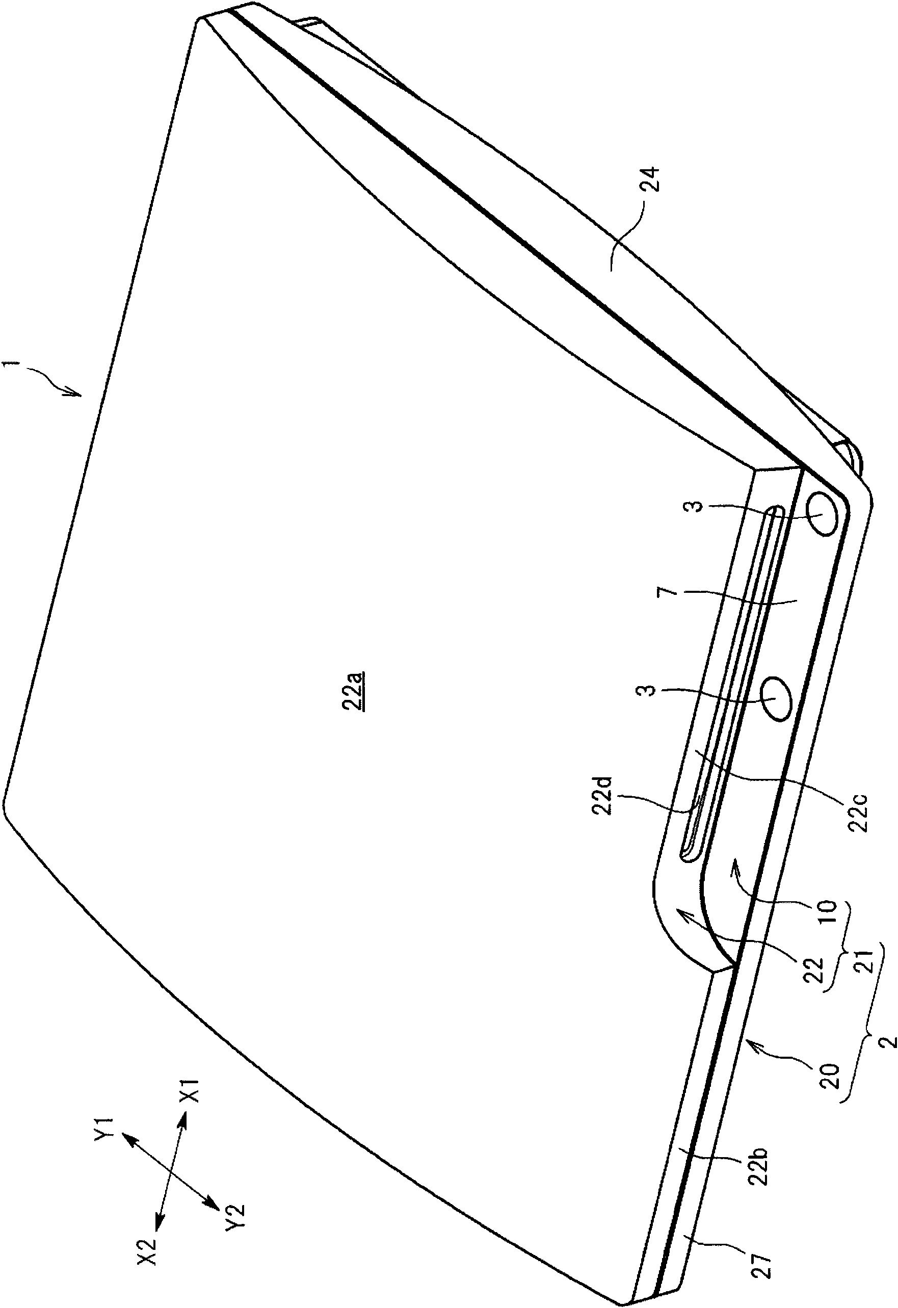
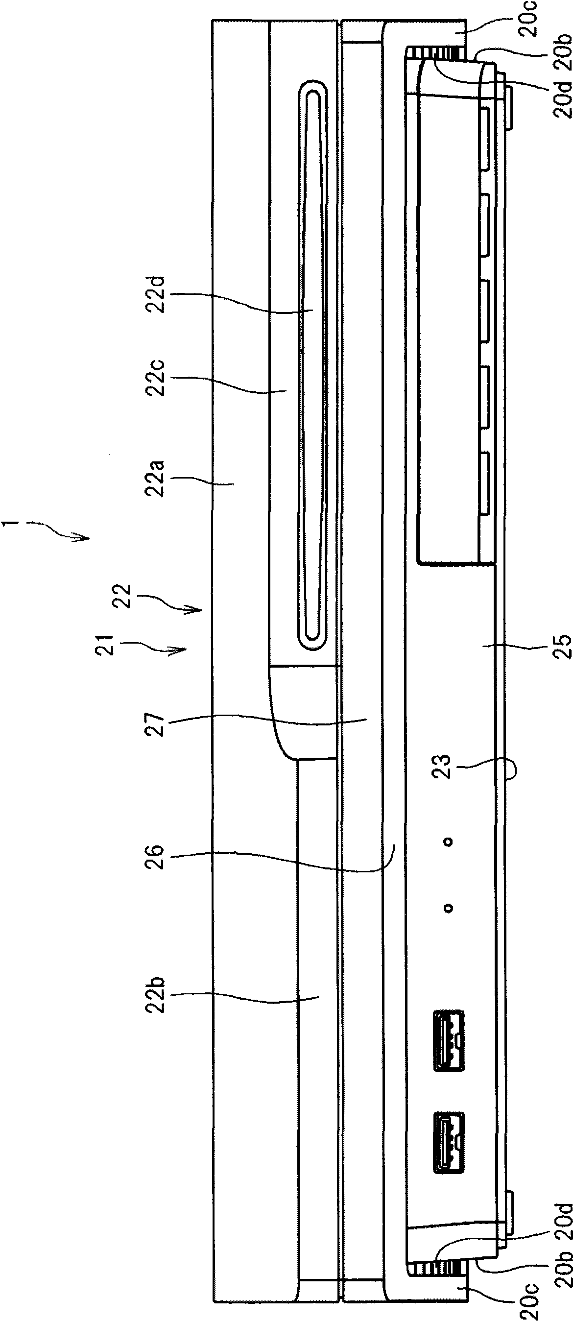
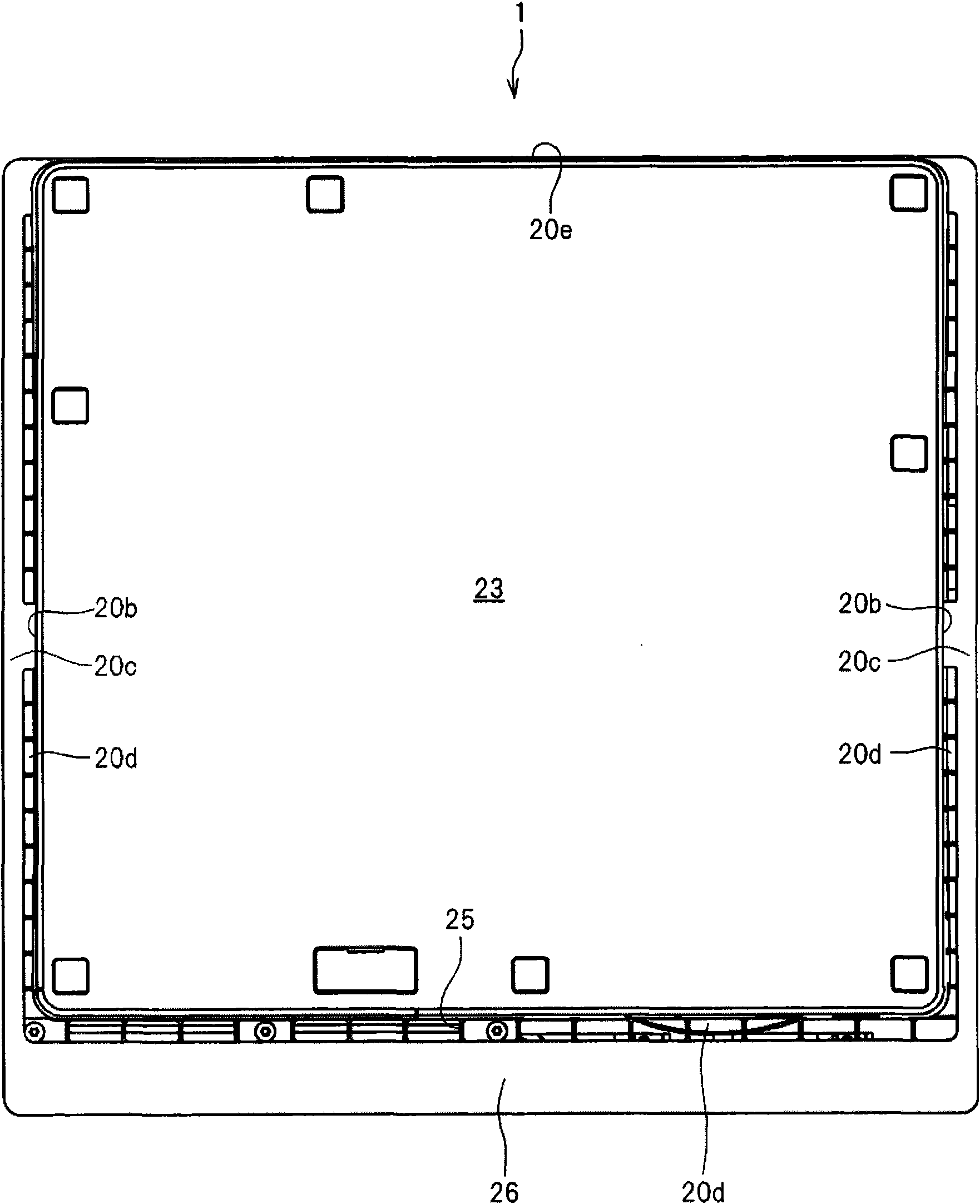
[0035] An embodiment of the present invention will be described below with reference to the accompanying drawings. figure 1 is a perspective view of an electronic device 1 according to an embodiment of the present invention; figure 2 is a front view of the electronic device 1; image 3 is a bottom view of the electronic device 1; Figure 4 is a rear view of the electronic device 1 . Figure 5 is an exploded perspective view of the case body 22 and the front panel 10 of the upper case 21 equipped with the electronic device 1 . Image 6 is an exploded perspective view of the front panel 10 . Figure 7 Yes Image 6 magnified view of . Figure 8 is along Figure 5 A sectional view taken along line VIII-VIII in . Figure 9 It is a perspective view of the front plate 10 seen from obliquely below. Figure 10 is a bottom view of the button 3 and the base plate 4.

[0036] like figure 1 , 2As shown in or 5, the electronic device 1 includes a casing 2 constituting its outer ...


PUM


Abstract

In order to provide an electronic apparatus capable of smooth operation of a press button, an electronic apparatus includes: an outer panel having a hole in which a press button is fitted and a circuit board placed on a back side of the outer panel; a stopper restricted from moving in the thickness direction of the outer panel is formed between the press button and the circuit board; the stopper is brought into contact with the flange portion formed on an edge of the press button when the press button has moved in the thickness direction of the outer panel.

Description

technical field [0001] The present invention relates to electronic devices such as game machines, audio-visual devices, and personal computers. Background technique [0002] Typically, electronic devices such as game consoles, audiovisual devices, personal computers, etc. are available. Some electronic devices (such as those in JP H8-36871 A) have buttons such as a power button, an eject button for ejecting a storage medium, etc., some of which are provided inside holes formed on a panel constituting the outer surface of the electronic device, so as to Move along the thickness of the panel. When the button is pressed to move in the thickness direction, the contacts formed on the circuit board provided on the back side of the panel are pressed to the button, thereby forming an electrical connection. [0003] In addition, existing electronic equipment (such as in JP 2008-103671 A) includes a case including a lower case formed to open upward, and an upper case provided on the...

Claims


Application Information

Patent Timeline
Patent Type & Authority Applications(China)
IPC IPC(8): H05K5/02
CPCH05K5/0217
Inventor 古坊贵行
Owner SONY INTERACTIVE ENTERTAINMENT INC
Learn More