Airflow blow and suction vibration cleaning method and device of engine cylinder cover

A technology for an engine cylinder head and a cleaning device, which is applied to cleaning methods using gas flow, engine components, machines/engines, etc., can solve problems such as high manufacturing and maintenance costs, aluminum scraps stuck in bends, and aluminum scraps retention. , to achieve the effect of solving the cleaning problem

Active Publication Date: 2010-10-20
DONGFENG PEUGEOT CITROEN AUTOMOBILE
View PDF3 Cites 20 Cited by
  • Summary
  • Abstract
  • Description
  • Claims
  • Application Information

AI Technical Summary

Problems solved by technology

Advantages: It has a good cleaning effect on the impurities and oil stains on the exposed surface of the parts (such as: the outer surface of the cylinder head, low-pressure oil chamber); Disadvantages: Cleans the sundries and oil stains in blind holes, deep holes and internal complex cavities Less than, almost no effect on the lumen
Advantages: all-round cleaning of parts, good cleaning effect on impurities and oil stains on the surface of parts (such as: outer surface of cylinder head, low-pressure oil chamber); disadvantages: cleaning of blind holes, deep holes and complex cavities The effect is not good, and there are still a lot of aluminum scraps remaining in it after cleaning;
Advantages: good cleaning effect on machined holes (such as: threaded holes, blind holes, main / horizontal / upper oil passages); Disadvantages: poor cleaning effect on complex-shaped cavities, the main reason is one-way flushing, aluminum chips on one side Light, one-sided teeth, it is easy to get aluminum chips stuck in the curve when washing in one direction, and it is difficult to wash out some small foreign matter such as molding sand deposited in the curve (such as: water channel)
Disadvantages: The cleaning effect of the cavity with complex shapes is not good. The main reason is that it acts in one direction, which can easily cause aluminum chips to get stuck at the bend
Disadvantage: a small amount of water enters the channel for the second time
Disadvantages: high manufacturing and maintenance costs, one-way action, and some aluminum chips are still stuck in narrow bends

Method used


Image

  • Airflow blow and suction vibration cleaning method and device of engine cylinder cover
  • Airflow blow and suction vibration cleaning method and device of engine cylinder cover
  • Airflow blow and suction vibration cleaning method and device of engine cylinder cover

Examples


Embodiment Construction

[0028] This embodiment is an explanation of the technical solution and claims of the present invention, and the protection scope of the present invention is not limited to the following structures.

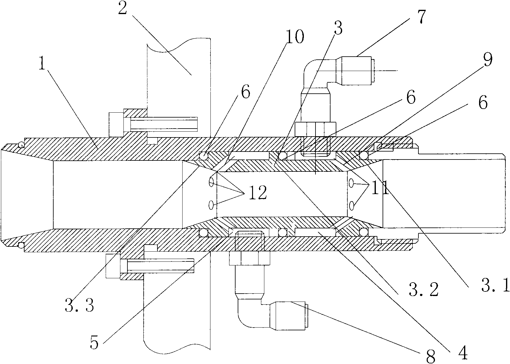
[0029] Such as figure 1 As shown, the engine cylinder head airflow blowing and oscillating cleaning device 30 includes an airflow channel tube 1 connected with a support plate 2; the airflow channel tube 1 is provided with a venturi tube 3, and the venturi tube 3 includes a contraction section 3.1, a throat tube 3.2, and Expand paragraph 3.3. The outer pipe wall of the venturi 3 is provided with a first air guiding groove 4 and a second air guiding groove 5 which are sealed and separated from each other. In this embodiment, the first air guiding groove 4 and the second air guiding groove 5 are along the axis It is also possible to arrange partitions on the same radial groove, and divide the same radial groove into two groove sections to form a first air guiding groove and a second ai...


PUM


Abstract

The invention relates to airflow blow and suction vibration cleaning method and device of an engine cylinder cover. The device comprises a Venturi tube. Air outlet pipelines are arranged in the expanding section and/or shrinkage section of the Venturi tube; the air outlet pipelines are communicated with an intake pipe; and the air outlets of the air outlet pipelines face the media flowing direction of the Venturi tube. By utilizing the device, two-direction alternate blow and suction cleaning is realized on box parts, such as the engine cylinder cover and the like, the problem that aluminium skimming jam and deposit at contracted type cavity bends, caused by the unidirectional characteristic of the traditional cleaning process, is solved, the cleaning problem of the aluminium skimmings iseffectively solved, and the cleanness demand of the product is satisfied.

Description

Technical field [0001] The invention belongs to the processing and cleaning technology of automobile parts, and particularly relates to the cleaning technology of the cutting and processing of engine cylinder heads. Background technique [0002] The internal cavity structure of the engine cylinder head is complicated in shape, with many corners and dead angles. After machining, it is easy to deposit and jam chips. Traditional cleaning methods for engine cylinder heads include: [0003] Spray cleaning, arranging dense spray pipes around the parts to be cleaned (or rotating the parts at the spray position) to perform spray cleaning on the entire parts. Advantages: It has a good cleaning effect on the impurities and oil on the exposed surface of the parts (such as: the outer surface of the cylinder head, low-pressure oil cavity); Disadvantages: Cleaning the sundries and oil on the blind holes, deep holes and internal complex cavities No, it has almost no effect on the inner cavity....

Claims


Application Information

Patent Timeline
Patent Type & Authority Applications(China)
IPC IPC(8): F02B77/04B08B5/02B08B5/04
Inventor 刘裕安
Owner DONGFENG PEUGEOT CITROEN AUTOMOBILE
Why Eureka
Try Eureka