Monitoring system and camera terminal

A monitoring system and camera technology, applied in the field of monitoring systems, can solve the problems of not being able to find intruders, not being able to move the camera at the same time for continuous monitoring, insufficient monitoring capabilities, etc., and achieve the effect of high monitoring capabilities

Active Publication Date: 2010-10-20
PANASONIC CORP
View PDF4 Cites 4 Cited by
  • Summary
  • Abstract
  • Description
  • Claims
  • Application Information

AI Technical Summary

Problems solved by technology

[0015] In addition, in the conventional technologies disclosed in the above-mentioned Patent Documents 1 to 4, since different tasks are assigned to each of the plurality of cameras, there is also a problem that monitoring blind spots are likely to occur, and the monitoring capability is insufficient.
[0016] For example, in the plurality of mobile cameras 10 constituting the monitoring system disclosed in the above-mentioned Patent Document 2, by moving along the track of the guide rail 20

Method used


Image

  • Monitoring system and camera terminal
  • Monitoring system and camera terminal
  • Monitoring system and camera terminal

Examples


Embodiment approach 1

[0191] First, Embodiment 1 of the present invention will be described.

[0192] Figure 9 It is a block diagram of the monitoring system in Embodiment 1 of this invention. This monitoring system includes a plurality of camera terminals 101, 101b composed of the same structural elements, and a communication medium 102 that transmits data related to the imaging characteristics of each camera terminal 101, 101b. Information, each camera terminal 101, 101b changes the imaging characteristics in coordination with the surrounding camera terminals, so that the entire monitoring system can monitor the entire monitoring area in more detail. Hereinafter, a description will be given focusing on one camera terminal 101 .

[0193] The camera terminal 101 is an autonomous coordination camera in the first embodiment.

[0194] The communication medium 102 is a communication network connecting a plurality of camera terminals.

[0195] The communication unit 103 is a communication interface...

Embodiment approach 2

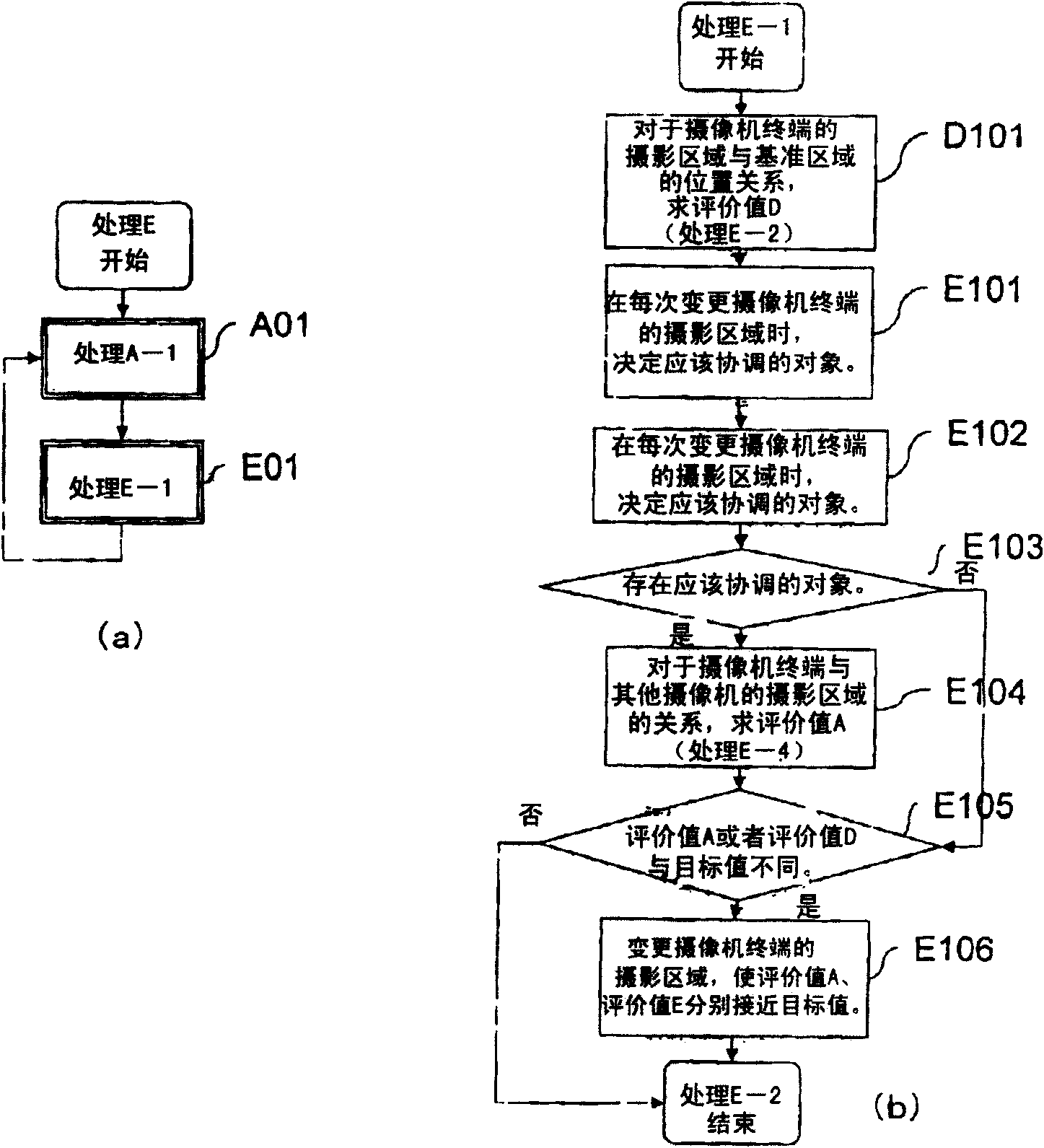
[0263]Next, Embodiment 2 of the present invention will be described.

[0264] Figure 20 It is a block diagram of the monitoring system in Embodiment 2 of this invention. This monitoring system includes a plurality of camera terminals 201, 201b composed of the same structural elements, and a communication medium 102 that transmits information related to the photographing characteristics of each camera terminal 201, 201b. The information is characterized in that, in addition to the control of the shooting area in Embodiment 1, each camera terminal also adjusts the shooting area so that it has a constant positional relationship with a predetermined reference area. In addition, a description will be given centering on one camera terminal 201 . exist Figure 20 in, with Figure 9 The same symbols are used for the same structural elements, and descriptions are omitted.

[0265] The camera terminal 201 is an autonomous coordination camera in the second embodiment.

[0266] The...

Embodiment approach 3

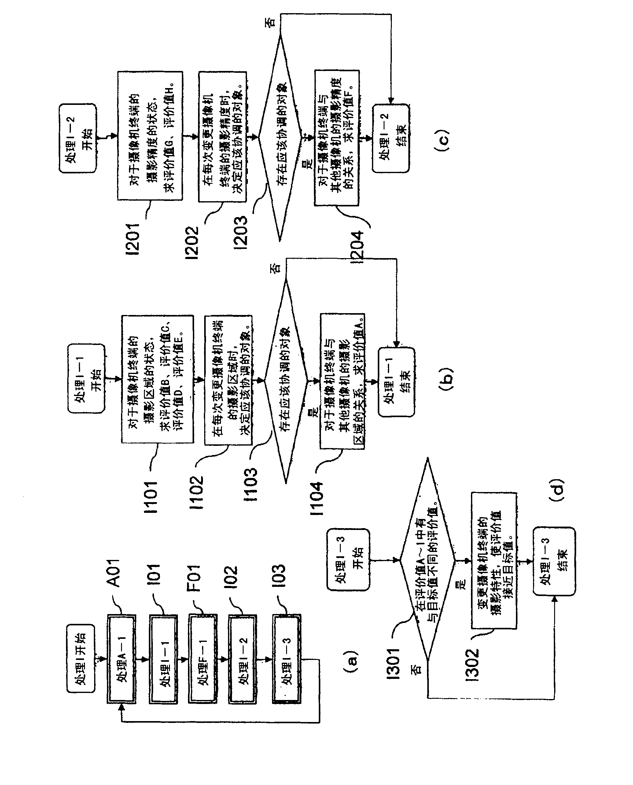
[0310] Next, Embodiment 3 of the present invention will be described.

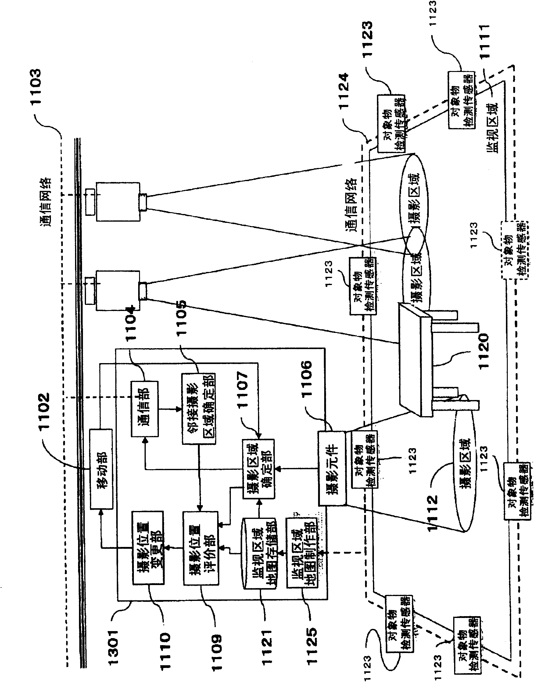
[0311] Figure 25 It is a block diagram of the monitoring system in Embodiment 3 of this invention. This monitoring system includes a plurality of camera terminals 301, 301b composed of the same structural elements, and a communication medium 102 that transmits information related to the photographing characteristics of each camera terminal 301, 301b. The information is characterized in that, in addition to the control of the shooting area in Embodiment 1, each camera terminal also adjusts the shooting area so that it has a constant positional relationship with the object existing in the monitoring area. Hereinafter, one camera terminal 301 will be described as a center. exist Figure 25 in, for with Figure 9 The same symbols are used for the same structural elements, and explanations are omitted.

[0312] The camera terminal 301 is an autonomous coordination camera in the third embodiment.

[0313]...


PUM


Abstract

There is provided a monitoring system capable of flexibly coping with a change of system configuration and having a high monitoring capability. The monitoring system includes a plurality of camera terminals (01, 01b) connected by a communication medium (02). The plurality of camera terminals include: an imaging element (04) for imaging an imaging region included in a monitoring range and having means for modifying the imaging region; a communication unit (03) for transmitting imaging characteristic information as information specifying an imaging region, via a communication medium (02) to another camera terminal and receiving imaging characteristic information from the another terminal; and an imaging characteristic modification unit (05) for modifying the imaging region by controlling the imaging element (04) of the camera terminal so that the imaging region of the camera terminal and the imaging region of the another camera terminal are in a predetermined relationship according to the imaging characteristic information from the camera terminal and the imaging characteristic information from the another camera terminal received by the communication unit (03).

Description

[0001] The application of the present invention is a divisional application submitted by the applicant on January 18, 2005, the application number is 200580004014.X, and the title of the invention is "surveillance system and camera terminal". technical field [0002] The present invention relates to a monitoring system composed of a plurality of camera terminals, and in particular to a monitoring system capable of monitoring the entire monitoring area and in which each camera terminal cooperates with surrounding camera terminals. Background technique [0003] By using multiple cameras, it is possible to perform high-function surveillance that cannot be realized with only one camera. [0004] Conventionally, as a monitoring system using a plurality of cameras, there is a technique disclosed in Patent Document 1, for example. figure 1 It is a structural diagram of an apparatus for automatically adjusting the detection areas of multiple cameras described in Patent Document 1. ...

Claims


Application Information

Patent Timeline
IPC IPC(8): H04N7/18G08B13/196
CPCG08B13/19608G08B13/19623G08B13/19643G08B13/19656G08B13/19695G08B13/19606H04N7/181
Inventor 吉田笃青木胜司荒木昭一
Owner PANASONIC CORP
Why Eureka
Try Eureka