
Display panel

A display panel and substrate technology, applied in nonlinear optics, instruments, optics, etc., can solve problems such as insufficient capacitive coupling effects

Active Publication Date: 2010-10-27
AU OPTRONICS CORP
View PDF3 Cites 0 Cited by
  • Summary
  • Abstract
  • Description
  • Claims
  • Application Information

AI Technical Summary

Problems solved by technology

[0004] The technical problem to be solved by the present invention is to provide a display panel, which can solve the problem of insufficient capacitive coupling effect between the floating electrode and the pixel electrode in the traditional FES liquid crystal display

Method used


Image

  • Display panel
  • Display panel
  • Display panel

Examples


Embodiment Construction

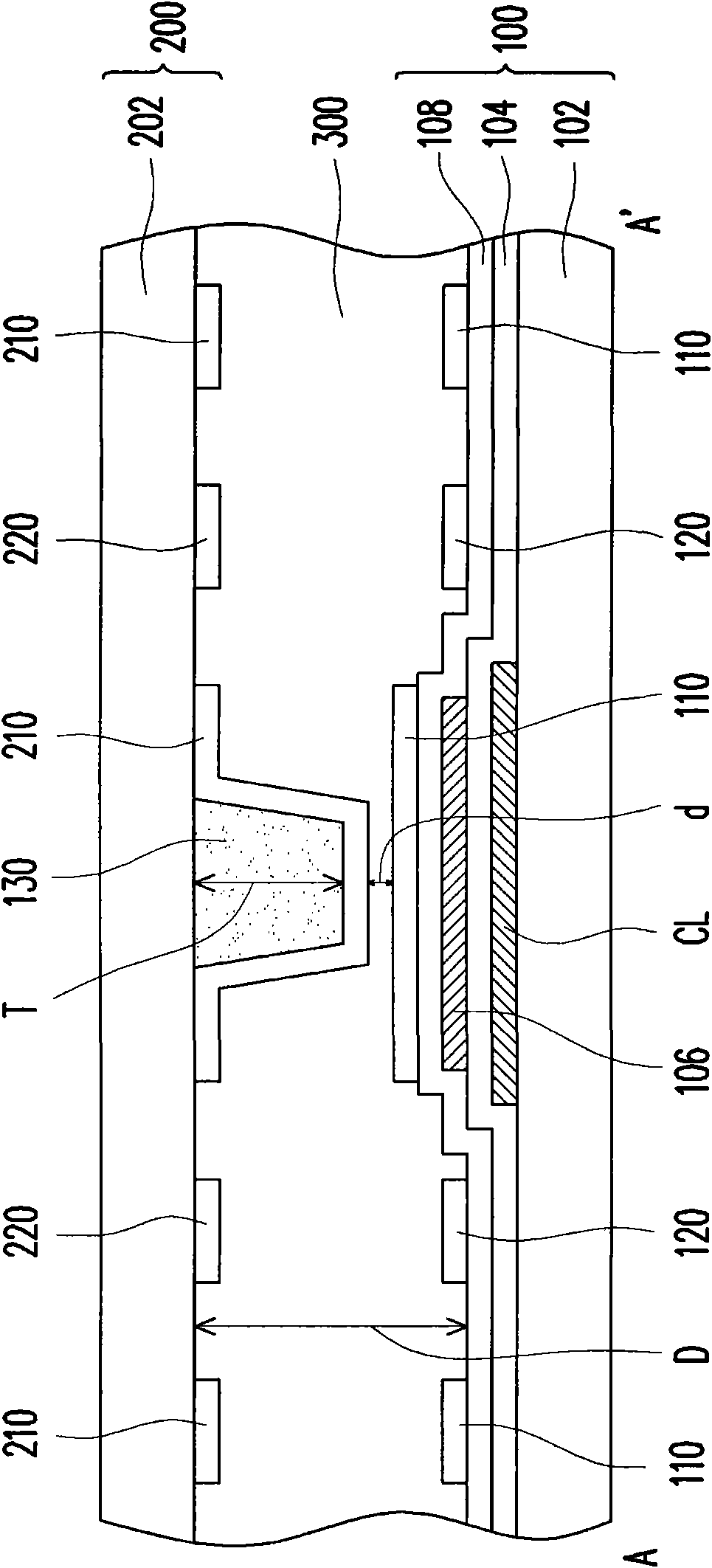
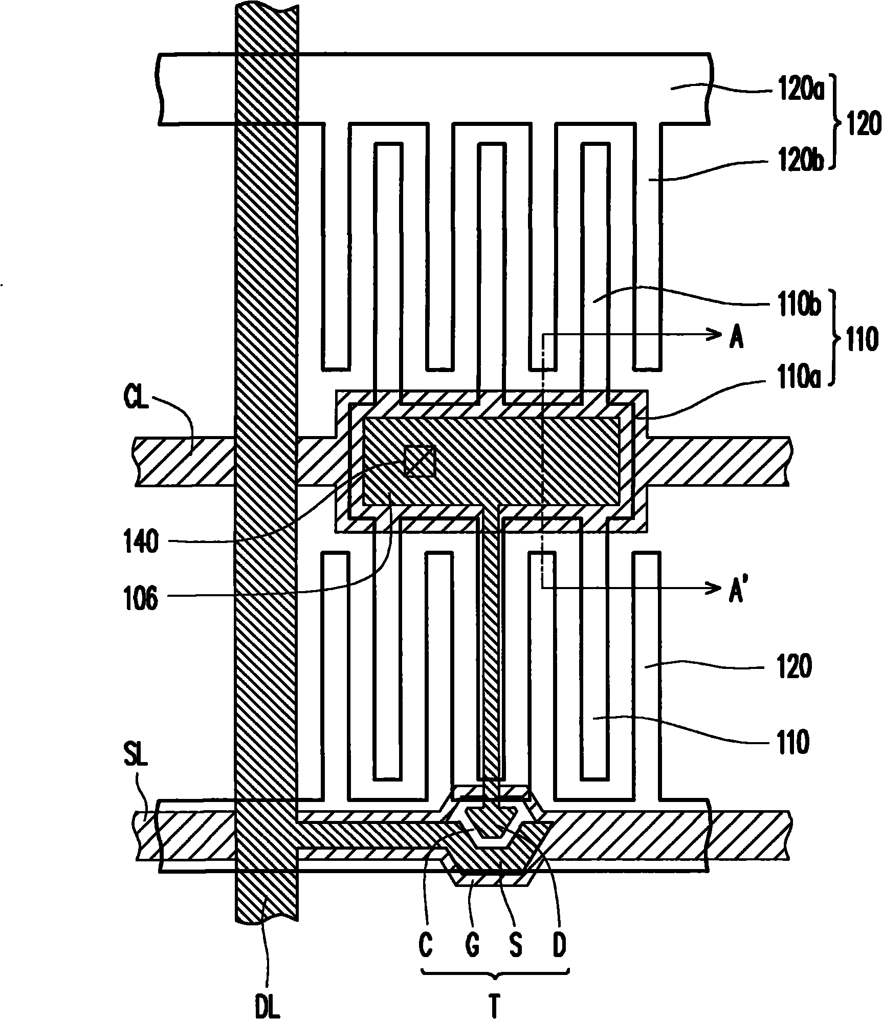
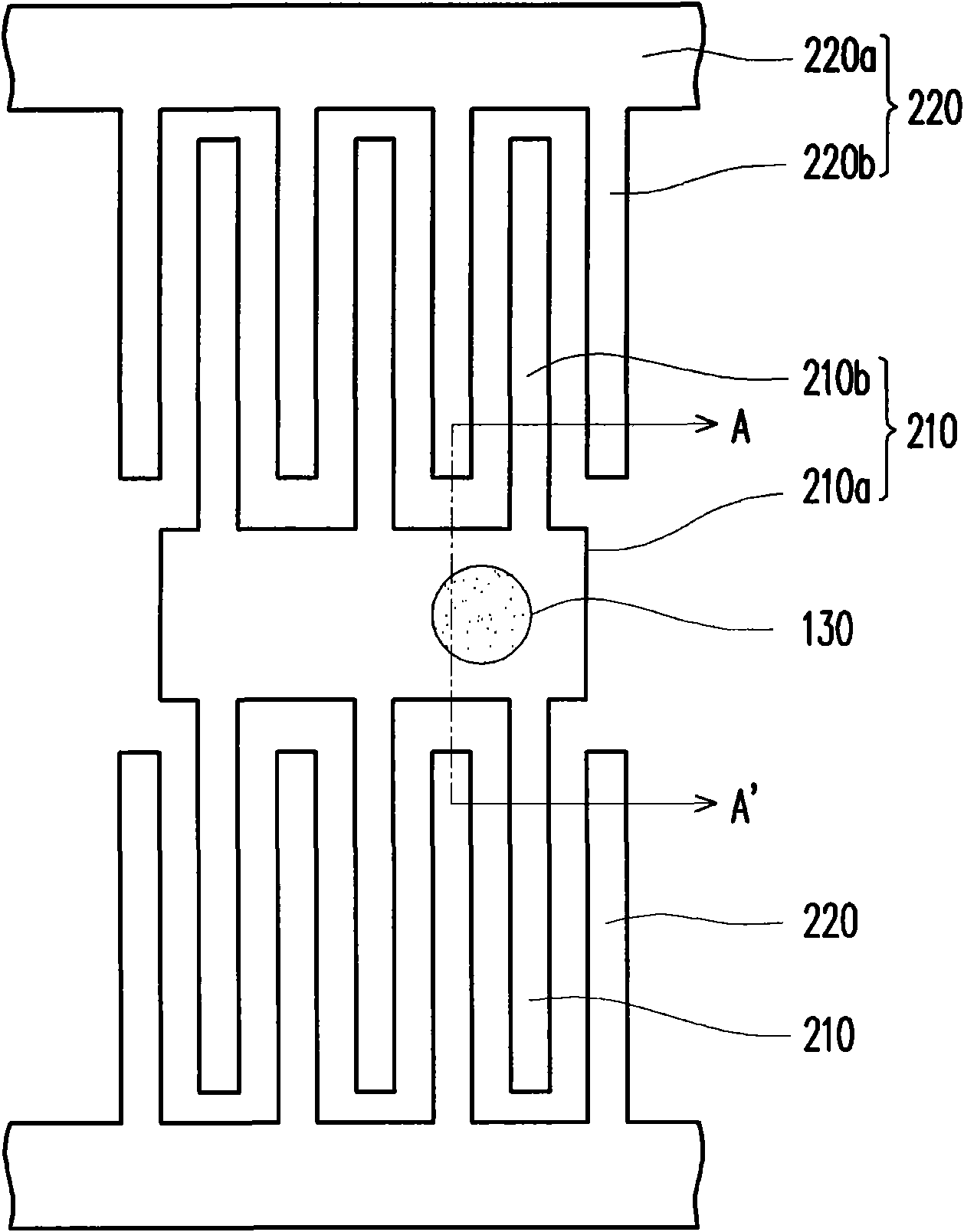
[0043] figure 1 It is a schematic cross-sectional view of a display panel according to an embodiment of the invention. Figure 2A Yes figure 1 Top view of the first substrate of the display panel. Figure 2B Yes figure 1 Top view of the second substrate of the display panel. especially, figure 1 Is corresponding Figure 2A versus Figure 2B Sectional view of the section line A-A'. In addition, the following figures only illustrate one of the pixel structures of the display panel as an example for illustration. Generally speaking, a display panel is composed of a plurality of pixel structures arranged in an array. Those skilled in the art should be able to understand the structure of the display panel according to the present invention based on the description of this specification and the drawings. Please also refer to figure 1 , Figure 2A as well as Figure 2B The display panel of this embodiment includes a first substrate 100, a second substrate 200, a spacer 130 between the...


PUM

PropertyMeasurementUnit
Thicknessaaaaaaaaaa

Abstract

The invention discloses a display panel, which comprises a first base plate, a second base plate, a spacer arranged between the first base plate and the second base plate, and display medium. The first base plate comprises a first substrate, a scanning line and a data line arranged on the first substrate, an active component electrically connected with the scanning line and the data line, a pixel electrode electrically connected with the active component, and a first shared electrode electrically insulated with the pixel electrode and configured with the pixel electrode in a staggering way. The second base plate comprises a second substrate, a second shared electrode arranged on the second substrate and configured corresponding to the first shared electrode of the first base plate, and a floating electrode electrically insulated with the second shared electrode and configured corresponding to the pixel electrode of the first base plate.

Description

Technical field [0001] The present invention relates to a display panel, and in particular to a floating electrode switching (FES) display panel. Background technique [0002] At present, the market for thin film transistor liquid crystal displays (TFT-LCD) is towards high contrast (contrastratio), no gray scale inversion (gray scale inversion), high brightness (brightness), high color saturation (color saturation), fast response (response) ) And wide viewing angle (viewing angle). Common wide viewing angle technologies include: twisted nematic liquid crystal (TN) plus wide viewing film (wide viewing film), in-plane switching (IPS) liquid crystal display, and fringe field switching (Fringe Field Switching) , FFS) LCD and Multi-domain Vertical Alignment (Multi-domain Vertical Alignment, MVA) LCD. [0003] In addition to the above-mentioned wide viewing angle liquid crystal displays, a floating electrode switching (FES) liquid crystal display has been developed. In FES liquid crys...

Claims


Application Information

Patent Timeline
IPC IPC(8): G02F1/1343G02F1/1339
Inventor 李明骏黄宏基李锡烈
Owner AU OPTRONICS CORP
Learn More