
Toilet stool with independent cleaning device

A toilet and stand-alone technology, applied in the field of sanitary ware, can solve problems such as complex structure, large paper consumption, and insufficient thoroughness, and achieve the effects of good cleaning effect, water saving and simple structure

Inactive Publication Date: 2012-05-30
陈克明
View PDF0 Cites 0 Cited by
  • Summary
  • Abstract
  • Description
  • Claims
  • Application Information

AI Technical Summary

Problems solved by technology

[0002] Cleaning the anus or vulva after going to the toilet is a well-known common sense. The usual method is to wipe it with toilet paper, but this method is often not thorough enough and consumes a lot of paper.
In order to change this situation, a toilet with a body cleaning device has appeared at present. This body cleaning device generally installs the shower head on the rear side of the toilet bucket wall, and it is unsightly and easy to install the shower head if it is too exposed. Contamination or damage, if the installation is too concealed, it will be inconvenient to use, especially not suitable for women when cleaning the vulva; in order to solve the shortage of this rear-mounted nozzle, generally the nozzle is raised at a certain angle so that the sprayed water It becomes a water column rushing upwards and forwards, but when the water pressure is low, the water column is weak and unsuitable, and when the water pressure is too high, the water column will rush out of the bucket and other problems.
In addition, this new type of toilet with body cleaning device generally has problems such as relatively complicated structure, high failure rate, and high price, and cannot meet the needs of the general public.

Method used


Image

  • Toilet stool with independent cleaning device
  • Toilet stool with independent cleaning device
  • Toilet stool with independent cleaning device

Examples


Embodiment Construction

[0013] Below in conjunction with accompanying drawing, structural principle of the present invention will be further described:

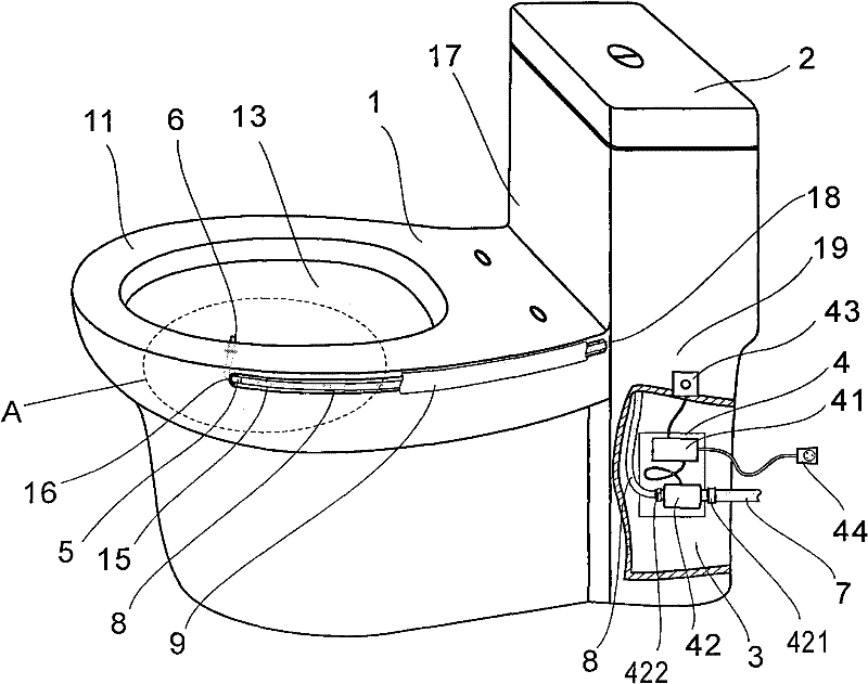
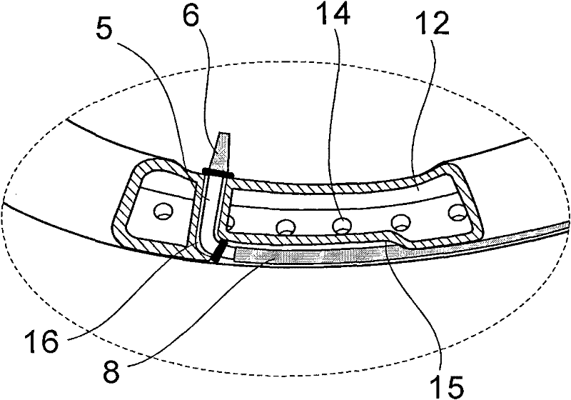
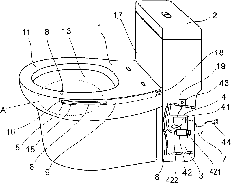
[0014] A toilet with a stand-alone body cleaning device, comprising a toilet body 1 and a water tank 2, and a space 3 below the water tank 2; , the flushing channel 12 is provided with a flushing hole 14 communicating with the barrel cavity 13, and a set of independent induction control body cleaning device 4 is also arranged in structure; The invisible groove 15, the front end of the invisible groove 15 reaches the front part of the barrel edge 11, and is provided with a front through hole 16 passing through the flushing channel 12 and penetrating into the bucket cavity 13, and the rear end of the invisible groove 15 reaches the rear wall of the toilet body 1 17, and is provided with a rear through hole 18 that passes through the rear wall 17 and communicates with the space 3 below the water tank 2; the front through hole 16 is isolated from the fl...


PUM


Abstract

The invention relates to a toilet stool with an independent cleaning device. An outer side wall at the toilet edge of a toilet stool body is provided with a concave invisible groove, the front end of the invisible groove is provided with a front through hole penetrating through a toilet cavity, a connecting bent pipe is installed in the front through hole, and one end of the connecting bent pipe,extending into the toilet cavity, is connected with a water spray nozzle; an inductive control cleaning device comprises a control circuit and an electromagnetic valve, a soft duct is laid along the invisible groove in an appressed way, one end of the soft duct is connected with the electromagnetic valve, and the other end is connected with the connecting bent pipe; and when the inductive controlcleaning device is in a standby state, an inductive switch is touched by a hand to enable the control circuit to work so as to ensure that the water spray nozzle begins spraying water, and when a preset time is up, water spraying is stopped. In the implementation of the invention, the water spray nozzle is installed in a concealing way without influencing a nice appearance; the inductive control cleaning device has simple structure, lower cost, convenient installation and no need of supporting facilities during installation; and because of the use of a touch sensitive delay controller, the invention not only has convenient use and good cleaning effect, but also is beneficial to saving water and a large amount paper products.

Description

technical field [0001] The invention relates to a sanitary appliance, in particular to a toilet with an independent body cleaning device. Background technique [0002] It is common knowledge that the anus or vulva are cleaned immediately after defecating. The usual method is to wipe with toilet paper, but this method is often not thorough enough and consumes a large amount of paper. In order to change this situation, a toilet with a body cleaning device has appeared at present. This body cleaning device generally installs the shower head on the rear side of the toilet bucket wall, and it is unsightly and easy to install the shower head if it is too exposed. Contamination or damage, if the installation is too concealed, it will be inconvenient to use, especially not suitable for women when cleaning the vulva; in order to solve the shortage of this rear-mounted nozzle, generally the nozzle is raised at a certain angle so that the sprayed water It becomes a water column rushin...

Claims


Application Information

Patent Timeline
Patent Type & Authority Patents(China)
IPC IPC(8): E03D9/08
Inventor 陈克明
Owner 陈克明
Learn More