Escape door lock

A technology of door locks and lock heads, which is applied in the field of locks, can solve problems such as difficult promotion, poor safety exit locking and evacuation channels, and safety exit control door locks have not been fully promoted and applied, so as to ensure the safety and reliability of anti-theft strong effect

Inactive Publication Date: 2010-11-10
马刘陈
View PDF4 Cites 5 Cited by
  • Summary
  • Abstract
  • Description
  • Claims
  • Application Information

AI Technical Summary

Problems solved by technology

[0002] For a long time, safety exit management has been troubled by the contradiction between public security management and fire protection management. From the perspective of security prevention, the stronger the exit lock, the better. From the perspective of accident escape, the smoother the safety passage, the more effective. Locking the safety door is a taboo for escape in an accident; according to statistics, most of the fire accidents that caused more casualties were caused by the locking of the safety exit or the poor evacuation passage; therefore, the control of the safety exit The problem has been widely concerned by firefighting technicians and managers of densely populated places, and the research on safety exit management has never stopped
[0003] In recent years, domestic and foreign countries have successively developed some safety exit control door locks. Although these products have solved the reliability of door opening, they have relatively large defects in the locking function of the door, so they are not used by managers in densely populated places. Optimistic, it is very difficult to promote, and the fundamental reason why the current safety exit control door locks have not been fully promoted and applied is this

Method used


Image

  • Escape door lock
  • Escape door lock
  • Escape door lock

Examples


Embodiment Construction

[0021] Below in conjunction with accompanying drawing and specific embodiment the present invention is described in further detail:

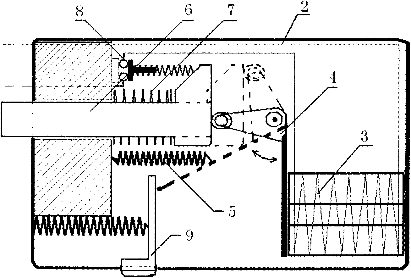
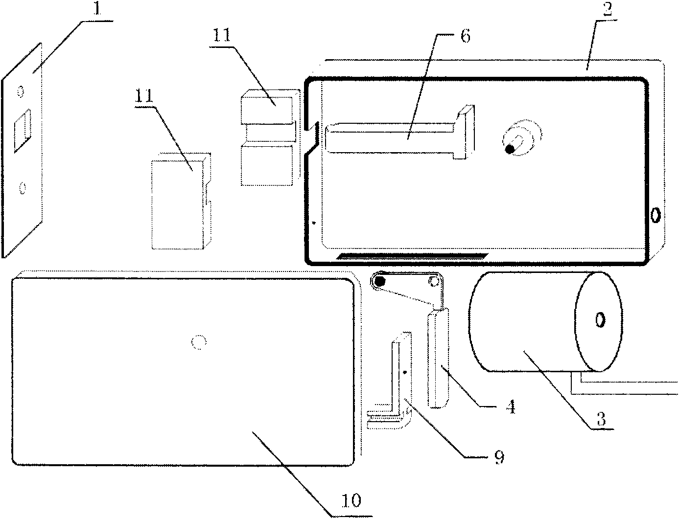
[0022] Such as figure 1 , figure 2 , image 3 , Figure 4 with Figure 5 Shown, a kind of escape door lock, it comprises lock shell 2, shell cover 10, the outlet of lock end that is arranged on lock shell 2, lock end 6, lock end slot 1, electromagnet 3, touch switch 8, lock Machine 4, dial block 9, suction plate return spring 5, dial block return spring and lock head return spring 7;

[0023] The lock 6 comprises a lock bar and a push block arranged at the end of the lock bar;

[0024] The lock 4 includes a push arm and an electromagnet suction plate arranged at one end of the push arm, the push arm and the electromagnet suction plate are arranged at an angle, and the angle is preferably a right angle;

[0025] The shifting block 9 includes a slot body and a dial arranged on the slot body;

[0026] Wherein, the electromagnet 3 and the to...


PUM


Abstract

The invention provides an escape door lock which comprises a lock shell, a shell cover, a lock head outlet, a lock head, a lock head groove, an electromagnet, a touch switch, a lock machine, a shifting block, a suction plate return spring, a shifting block return spring and a lock head return spring, wherein the lock head comprises a lock head rod and a pushing block; the lock machine comprises a pushing arm and an electromagnet suction plate; the shifting block comprises a trough body and a shifting plate; the touch switch is arranged corresponding to the pushing block, the touch switch is connected with the electromagnet, and the pushing arm is hinged with the inner wall of the lock shell; a shifting notch is formed on the lock shell, and the trough body is arranged in the shifting notch; the suction plate return spring is connected between the lock shell and the electromagnet suction plate; the shifting block return spring is connected between the lock shell and the shifting plate; the lock head return spring is sleeved on the lock head rod and is propped between the lock shell and the pushing block; and the electromagnet suction plate is arranged corresponding to the shifting plate, the electromagnet suction plate is arranged corresponding to the electromagnet, and the pushing arm is pushed on the pushing block. The door lock has the advantages of convenient use, firm locking, safety and reliability and is convenient for opening a door.

Description

technical field [0001] The invention relates to a lock, in particular to an escape door lock for fire protection. Background technique [0002] For a long time, safety exit management has been troubled by the contradiction between public security management and fire protection management. From the perspective of security prevention, the stronger the exit lock, the better. From the perspective of accident escape, the smoother the safety passage, the more effective. Locking the safety door is a taboo for escape in an accident; according to statistics, most of the fire accidents that caused more casualties were caused by the locking of the safety exit or the poor evacuation passage; therefore, the control of the safety exit The problem has always been widely concerned by firefighting technicians and managers of densely populated places, and the research on safety exit management has never stopped. [0003] In recent years, domestic and foreign countries have successively devel...

Claims


Application Information

Patent Timeline
Patent Type & Authority Applications(China)
IPC IPC(8): E05B65/10E05B47/02E05B17/22
Inventor 马刘陈马圆棓袁天馗万良军李晓亚
Owner 马刘陈
Why Eureka
Try Eureka