Buffer arrangement and buffer stop of an elevator

A shock absorber and elevator technology, which is applied to elevators, lifting equipment in mines, transportation and packaging, etc., can solve expensive and slow problems, achieve fast and easy actuation, avoid modification work, and improve work safety Effect

Inactive Publication Date: 2015-01-07
KONE CORP
View PDF5 Cites 0 Cited by
  • Summary
  • Abstract
  • Description
  • Claims
  • Application Information

AI Technical Summary

Problems solved by technology

However, deepening the well pit is expensive and slow in nature

Method used


Image

  • Buffer arrangement and buffer stop of an elevator
  • Buffer arrangement and buffer stop of an elevator
  • Buffer arrangement and buffer stop of an elevator

Examples


Embodiment Construction

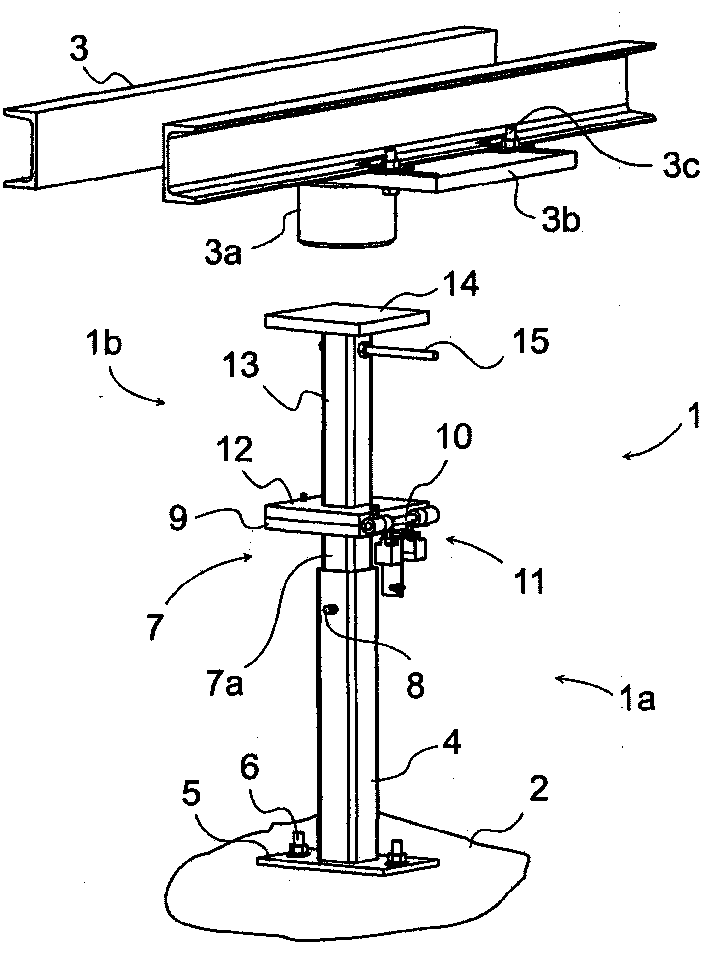
[0018] figure 1 One shock stop 1 is shown for use in the arrangement according to the invention when the elevator is in maintenance mode. In this solution, the shock stop 1 is fixed to the ground 2 of, for example, an elevator shaft and is arranged to point substantially vertically upwards. Other parts incorporated into the buffer configuration can be found in figure 1 Viewed above the breaker 1, these parts are fixed to the bottom beam 3 of the car hanger of the elevator car. These other parts are, among other things, the actual buffer 3a and the mounting base 3b of the buffer and the fixing means 3c by which the mounting base 3b is fixed to the bottom beam 3 of the car hanger. The bumper 3a may be an elastomeric bumper made of polyurethane, for example. The mounting base 3b of the buffer 3a is provided with e.g. an elongated fixing hole, thanks to which the mounting base 3b and at the same time the buffer 3a can be moved in a lateral direction into a better position, e.g....


PUM


Abstract

A buffer arrangement of an elevator includes at least a buffer of the elevator and a buffer stop, which includes at least a stem part fixed to its base and a stop element with adjustable height position fitted in connection with the stem part. The stop element includes a stopping surface for the buffer of the elevator. An extension part is in connection with the buffer stop for increasing the height position of the stopping surface of the buffer stop.

Description

technical field [0001] The invention relates to a buffer arrangement of an elevator and a shock stopper of an elevator. Background technique [0002] In old buildings, the shaft pit at the bottom of the elevator shaft often does not meet modern safety requirements, for example for the maintenance of elevators, since the height of the shaft pit is often too small for the new safety requirements. In retrofitting, it is often necessary to simultaneously adopt new elevator safety standards, in which case the old pit at the bottom of the elevator shaft must be deepened when it is too shallow, so that the new more stringent safety standards can be met. However, deepening the well pit is expensive and slow in nature. Contents of the invention [0003] The object of the present invention is to eliminate the above-mentioned disadvantages and to achieve a simple and low-cost elevator buffer arrangement, which makes it possible for those elevators which are to be retrofitted to also...

Claims


Application Information

Patent Timeline
Patent Type & Authority Patents(China)
IPC IPC(8): B66B5/28B66B5/00
CPCB66B5/28B66B5/288B66B19/007B66B5/0056
Inventor 朱哈·塔维拉
Owner KONE CORP
Why Eureka
Try Eureka