Control method of concrete pouring compactness for anchor backing plate by post-tensioning method

The technology of the backing plate under the anchor and the control method is applied in the direction of manufacturing tools, ceramic molding machines, etc., which can solve the problems of difficult control of the concrete vibration compactness, rupture of the anchor bottom plate, scrapping of the concrete components, etc., and achieve the vibration compactness Science, improve quality, avoid the effect of being crushed and cracked

Inactive Publication Date: 2011-12-14
CHINA METALLURGICAL CONSTR ENG GRP
View PDF0 Cites 0 Cited by
  • Summary
  • Abstract
  • Description
  • Claims
  • Application Information

AI Technical Summary

Problems solved by technology

[0004] The above-mentioned post-tensioning method for prefabricating reinforced concrete prestressed components mainly has the following disadvantages: after the concrete is injected into the mold cavity at the prestressed tension hole, the operator only controls the vibrating head of the vibrator to control the vibrating and compacting of the concrete If human negligence occurs, the concrete will not be compacted, and a cavity will be formed behind the anchor plate. The backing plate under the anchor is broken by pressure, which is prone to safety accidents and even causes the concrete components to be scrapped. Therefore, this method is not easy to control the vibration density of concrete, and it is extremely unscientific

Method used


Image

  • Control method of concrete pouring compactness for anchor backing plate by post-tensioning method
  • Control method of concrete pouring compactness for anchor backing plate by post-tensioning method
  • Control method of concrete pouring compactness for anchor backing plate by post-tensioning method

Examples


Embodiment Construction

[0014] The present invention will be described in further detail below in conjunction with the accompanying drawings and specific embodiments.

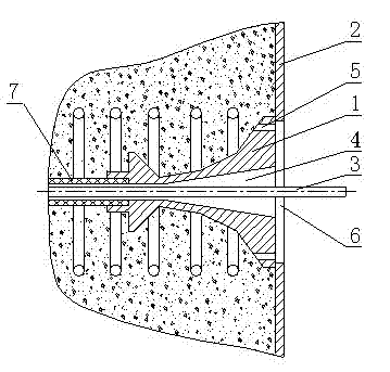
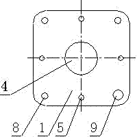
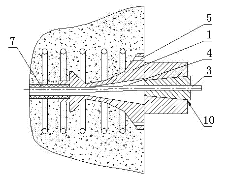
[0015] figure 1 For adopting the method of the present invention to carry out the structural representation of vibrating compactness control, figure 2 It is the front view of the backing plate under the anchor, as shown in the figure. The method for controlling the pouring density of the backing plate under the post-tensioning method is to pre-embed the bellows 7, and use the inner hole of the bellows 7 as a prestressed tension hole; The middle part of the lower backing plate 1 is provided with a central hole 4, and four overflow holes 5 are symmetrically and evenly distributed on the upper, lower, left and right sides of the anchor lower backing plate 1 relative to the central hole 4, and the anchor lower backing plate 1 is also provided with The bolt holes 8 and the grouting holes 9 are installed on the formwork 2 through bolt co...


PUM


Abstract

The invention discloses a control method of concrete pouring compactness of an anchor backing plate by a post-tensioning method, which comprises the following steps: embedding the anchor backing plate at the outer end of a pre-stressing tensioning hole; installing the anchor backing plate on a template; enabling a steel strand in the pre-stressing tensioning hole to pass through a center hole of the anchor backing plate and the template; arranging an overflow hole on the anchor backing plate; arranging an opening for exposing the overflow hole on the template; after concrete is poured into a mold cavity at the pre-stressing tensioning hole, vibrating by a vibrator and observing whether concrete slurry outflows from the overflow hole; if the concrete slurry does not outflow, continuing vibrating; and if the concrete slurry outflows, blocking the overflow hole with a core plug. The invention is more scientific and accurate to judge the concrete vibrating compactness according to whetherthe concrete slurry is in the overflow hole, completely avoids cavities formed in the anchor backing plate, and simultaneously avoids the phenomenon that the anchor backing plate is crushed in the process of pre-stressing tensioning, thereby increasing the quality of a concrete member, increasing the safety, eliminating the air bubbles on the surface of the concrete, and further improving the finish of the surface after the concrete is demolded.

Description

technical field [0001] The invention relates to a method for controlling the pouring density of concrete, in particular to a method for controlling the pouring density of concrete for backing plates under post-tensioning anchors. Background technique [0002] In the construction industry, especially in the professional construction of roads and bridges, post-tensioning method is generally used to prefabricate reinforced concrete prestressed components in design, and prestressed tension is implemented. [0003] In the prior art, the method of post-tensioning prefabricated reinforced concrete prestressed components is as follows: first, pre-embed the bellows, and use the inner hole of the bellows as the prestressed tension hole; then, pre-embed the anchor at the end of the prestressed tension hole The backing plate under the anchor is installed on the formwork through bolt connection, so that the steel strand in the prestressed tension hole passes through the center hole of th...

Claims


Application Information

Patent Timeline
Patent Type & Authority Patents(China)
IPC IPC(8): B28B1/04
Inventor 陈国民
Owner CHINA METALLURGICAL CONSTR ENG GRP
Why Eureka
Try Eureka