Backing plate under anchorage for post-tensioning method

A technology of under-anchor backing plate and post-tensioning method, which is applied to bridge parts, structural elements, bridges, etc., can solve the problems of under-anchor backing plate breakage, scrapped concrete components, and non-compact concrete, etc., achieving scientific structural design and improving quality , The effect of eliminating air bubbles

Inactive Publication Date: 2010-12-01
CHINA METALLURGICAL CONSTR ENG GRP
View PDF4 Cites 9 Cited by
  • Summary
  • Abstract
  • Description
  • Claims
  • Application Information

AI Technical Summary

Problems solved by technology

The under-anchor backing plate of this structure mainly has the following disadvantages in use: after the under-anchor backing plate is installed and fixed on the formwork, a concrete pouring closure is formed, and after the concrete is injected into the mold cavity at the prestressed tension hole, the operation Personnel only control the vibrating head of the vibrator to control the compactness of the concrete by experience. If human negligence occurs, the concrete will not be dense, so that a cavity will be formed behind the backing plate under the anchor. It is possible that the anchorage may press the backing plate under the anchor inward, and the backing plate under the anchor may be crushed, which is prone to safety accidents and even causes the concrete components to be scrapped

Method used


Image

  • Backing plate under anchorage for post-tensioning method
  • Backing plate under anchorage for post-tensioning method
  • Backing plate under anchorage for post-tensioning method

Examples


Embodiment Construction

[0012] The present invention will be described in further detail below in conjunction with the accompanying drawings and specific embodiments.

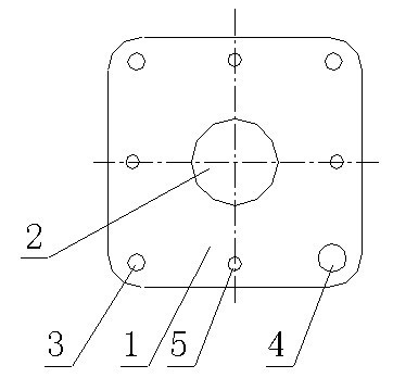
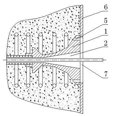
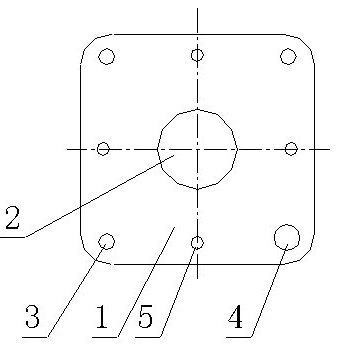
[0013] figure 1 It is the front view of the backing plate under the post-tensioning anchor of the present invention, figure 2 It is a schematic diagram of the structure of the backing plate under the post-tensioning method of the present invention in use, as shown in the figure. The post-tensioning anchor base plate is provided with a central hole 2 in the middle of the anchor base plate 1, and the anchor base plate 1 is provided with three installation and fixing holes 3 and a grouting hole 4, and the upper anchor base plate 1 , down, left and right and four overflow holes 5 symmetrically distributed relative to the center hole 2, the axis distance of the overflow holes 5 from the center hole 2 is less than the radius of the steel strand perforation 7 of the template 6, that is, the template The edge of the steel strand perforatio...


PUM


Abstract

The invention discloses a backing plate under anchorage for a post-tensioning method. The middle of the backing plate under anchorage is provided with a center hole, and an installation fixing hole, a mudjacking hole and an overflow hole are also arranged in the backing plate under anchorage, wherein the distance between the overflow hole and the axis of center hole is less than the radius of a steel strand perforation of a template. By arranging the overflow hole in the backing plate under anchorage, the invention realizes that the vibration compactness of concrete can be judged according to whether concrete grout flows out of the overflow hole after injecting the concrete into a mold cavity at a prestress tensioned hole and vibrating the concrete with a vibrator. If no concrete grout flows out, the result indicates that the concrete is incompact and needs to be further vibrated; and if the concrete grout flows out, the result indicates that the concrete is compact. The backing plate under anchorage is more scientific in structural design, completely avoids the formation of holes behind the backing plate under anchorage, simultaneously prevents the backing plate under anchorage from being broken by pressure in the prestress tensioning process, improves both the quality and the safety of concrete members, and eliminates bubbles on the concrete surface so as to further improve the surface finish after concrete demolding.

Description

technical field [0001] The invention relates to an anchor underlayment, in particular to a post-tensioning anchor underlayment. Background technique [0002] In the construction industry, especially in the professional construction of roads and bridges, post-tensioning method is generally used to prefabricate reinforced concrete prestressed components in design, and prestressed tension is implemented. The method of post-tensioning prefabricated reinforced concrete prestressed components is as follows: firstly, the corrugated pipe is pre-embedded, and the inner hole of the corrugated pipe is used as the prestressed tension hole; The lower backing plate is installed on the outer formwork through bolt connection, so that the steel strand in the prestressed tension hole passes through the center hole of the lower backing plate and the formwork; then, pour concrete into the formwork at the prestressed tension hole After entering the cavity, vibrate with a vibrator; then, after t...

Claims


Application Information

Patent Timeline
Patent Type & Authority Applications(China)
IPC IPC(8): E01D19/00E04C5/12
Inventor 陈国民
Owner CHINA METALLURGICAL CONSTR ENG GRP
Why Eureka
Try Eureka